STV32 · STV36 · STV40, WSM ELECTRICAL SYSTEM
9-S32
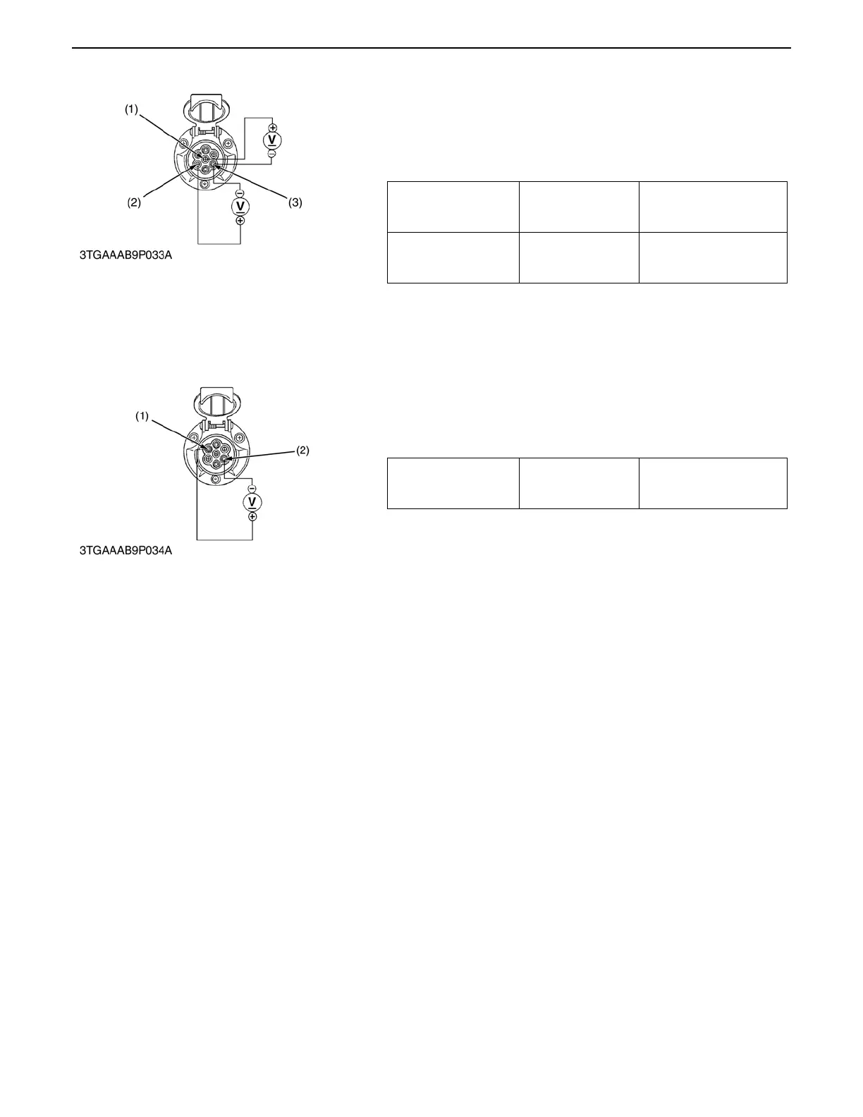
2) Tail Terminals
1. Turn the main switch ON, and measure the voltage with
voltmeter across the 7 terminal (1) and 3 terminal (3), and
across the 5 terminal (2) and 3 terminal (3).
2. If the voltage differs from the battery voltage, the wiring
harness or switches for tail lights are faulty.
3) Brake Light Terminals
1. Turn the main switch ON, and measure the voltage with
voltmeter across the 6 terminal (1) and 3 terminal (2).
2. If the voltage differs from the battery voltage, the wiring
harness or switch for brake lights are faulty.
Voltage (Head light
switch at ON, or position
switch at ON)
7 Terminal (Yellow /
Blue) - 3 Terminal
(Black)
Approx. battery voltage
Voltage (Head light
switch at ON, or position
switch at ON)
5 Terminal (Blue /
White) - 3 Terminal
(Black)
Approx. battery voltage
(1) 7 Terminal (3) 3 Terminal
(2) 5 Terminal
0000001806E
Voltage (When stepping
the brake pedal)
6 Terminal (Yellow /
Black) - 3 Terminal
(Black)
Approx. battery voltage
(1) 6 Terminal (2) 3 Terminal
0000001807E
 Loading...

