GENERAL
Page 12
505023M 08/11
Common System Component Wiring
Use thermostat wire to connect dampers, damper trans-
formers, and the DAS probe with the zone control system.
IMPORTANT
Avoid running any control wiring close to AC house
wiring. If this cannot be avoided, limit close parallel
of power and control wiring to a few feet.
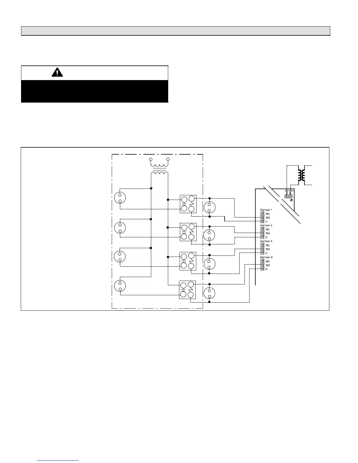
Dampers and Damper Transformer Wiring
Connect dampers to the zone control panel as shown in
figure 10. A total of six dampers may be connected at the
damper output terminals on the zone control panel. If addi-
tional dampers are used, additional transformers and re-
lays will be needed.
Fuse F1 will protect the damper outputs from a short circuit
or overload in the damper wiring.
If dampers are applied to the return duct system, the
dampers for each zone must be wired in parallel. Connect
damper transformer to zone control panel terminal block.
Refer to the Extended Damper Wiring section in figure 10
for wiring connections.
Discharge Air Sensor (DAS) Probe Wiring
Wire discharge air sensor probe to zone control panel. The
variable immersion-temperature probe is not polarity sen-
sitive.
120
VAC
24
VAC
EXTENDED
DAMPER
TRANSFORMER
(SEE NOTE)
(NOT TO EXCEED
75 VA) CLASS II
WIRING
120 VAC
24 VAC
ZONE
RELAY K4
ZONE
RELAY K3
ZONE
RELAY K2
ZONE
RELAY K1
ZONE 1
DAMPER
ZONE 2
DAMPER
ZONE 3
DAMPER
ZONE 4
DAMPER
EXTENDED
ZONE 1
DAMPER
EXTENDED
ZONE 2
DAMPER
EXTENDED
ZONE 3
DAMPER
EXTENDED
ZONE 4
DAMPER
NOTE − The extended damper
transformer rating should be sized to
adequately handle zone dampers
(1−4) plus relays (K1−K4) not to
exceed class II wiring limit of 75 VA.
Combined load of zone dampers and
zone relays not to exceed 60VA.
Use Lennox Part 56L68 for Zone
Relays 1 through 4.
EXTENDED
DAMPER
WIRING
ZONE CONTROL,
THERMOSTATS,
& DAMPERS
TRANSFORMER
Figure 10. Damper and Extended Damper Wiring Diagram

 Loading...


