GENERAL
Page 14
505023M 08/11
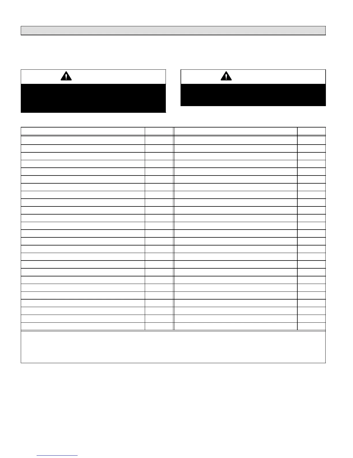
Minimum CFM in Variable Speed Furnace and Air Handlers
Harmony IIIt Zone Control system minimum CFM values for variable speed furnaces are listed in table 6. These apply to
furnaces and air handlers with serial numbers indicating they were built in 2004 or later. With furnaces built before 2004, use
the Harmony II
®
Zone Control system minimum air note in the installation instructions or engineering handbook for that
furnace or air handler’s air handling data.
CAUTION
This unit is manufactured using unpainted metal.
Sharp sheet metal edges can cause injury. When
installing the unit, avoid accidental contact with
sharp edges.
CAUTION
The control’s surfaces may be hot! Take care when
making wiring connections. Failure to do so may re-
sult in personal injury.
Table 6. Minimum CFM for Harmony IIIt Zone Control system with Variable Speed Blower Motors
Unit Model Number
CFM (min)
Unit Model Number
CFM (min)
G60DFV−36A−070 426 **SLP98xx070V36B 1/2HP motor 300
G60DFV−36B−090 523 **SLP98xx090V36C 1/2HP motor 250
G60DFV−60C−090 520 **SLP98xx090V48C 3/4HP motor 380
G60DFV−60C−110 475 **SLP98xx090V60C 1HP motor 450
G60DFV−60D−135 477 **SLP98xx110V60C 1HP motor 450
G60UHV−36A−070 426 **SLP98UH135V60D 1HP motor 450
G60UHV−36B−090 453 SL280xxV 3−ton 250
G60UHV−60C−090 478 SL280xxV 4− & 5−ton 450
G60UHV−60C−110 483 EL296xxV 2 & 3−ton 250
G60UHV−60D−135 495 EL296xxV 4−ton 380
G61MPV−36B−045 442 EL296xxV 5−ton 450
G61MPV−36B−070 458 CB31MV−41 380
G61MPV−36B−071 458 CB31MV−51, −65 399
G61MPV−36C−045 442 CBX32MV−018/024, CBX32MV−024/030 Rev 06 300
G61MPV−36C−090 479 CBX32MV−036 Rev 06 300
G61MPV−60C−090 449 CBX32MV−048, −060, −068 Rev 06 300
G61MPV−60C−091 458 **CBX40UHV−024, −030 250
G61MPV−60C−110 463 **CBX40UHV−036 380
G61MPV−60C−111 458 **CBX40UHV−042, −048, −060 450
G61MPV−60D−135 470 CBWMV (all models) 400
**G71MPP−36B−070 250
**G71MPP−36C−090 250
**G71MPP−60C−090 450
**G71MPP−60C−110 450
**G71MPP−60D−135 450
* A 3% duty cycle corresponds to the minimum CFM, and a 97% duty cycle corresponds to the maximum CFM.
** On G71MPP & SLP98 Furnaces and CBX40UHV and CBX32MV revision 06 Air Handlers, listed values in the table corre-
spond to 0% duty cycle of the Harmony IIIt Zone Control system control signal. Since the Harmony IIIt Zone Control system
puts 3% at minimum, actual value may be 10−30 CFM higher.
xx: UH = up/horizontal flow; DF = down flow

 Loading...


