TROUBLESHOOTING
Page 56
505023M 08/11
Blower Speed Checkout
The indoor blower speed should vary as zone demand changes. The fan speed LED varies in brightness as the blower
varies in speed. The brighter the LED, the more CFM being delivered. Blower speed can also be viewed by attaching an
electronic voltmeter between DS and any C terminal on the zone control panel. While not a precise measurement, the volt-
meter fluctuation indicates that the blower speed is changing.
1. Connect electronic voltmeter between DS and any C terminal on the zone control panel. Leave all field wiring in place.
2. Select DC volts scale.
3. Start zone heating or cooling checkout procedure.
4. Observe voltages:
D 22 volts DC = high speed (varies depending on input voltage at primary transformer).
D 11 volts DC (approx.) = medium speed 50% into adjustment band of blower.
D 0 volts DC = low speed or off.
All speeds in between are a percentage of 22VDC.
5. Also measure voltage at the indoor unit between DS and C. If the voltage is lower than the voltage measured at the
Harmony zone panel and/or the blower runs at a minimum fan speed, check and make sure C on the indoor unit is
connected to C on the zone panel transformer connection.
NOTE − G71MPP & SLP98 furnace models are equipped with an LED on the integrated control which displays blower airflow
in all modes of operation. See G71MPP & SLP98 installation instructions for additional information.
NOTE − CBX40UHV and CBX32MV Rev 06 have an LED display that will indicate the unit air volume. A" followed by the
number indicates the cfm. For example, A−2−0−0−5" indicates 2005 cfm.
NOTE − If blower operates only at the minimum cfm or will not ramp to zone air volume, check and make sure terminal C" on
the indoor unit terminal strip is connected to Harmony 24 VAC terminal C" (see figures 17 through 26).
NOTE − If blower hunts", check and make sure there is no connections on Y1 or Y2 on the indoor unit terminals strip (see
figures 17 through 26).
NOTE − Units without a 7−Segment LED will have a cfm" LED to indicate blower airflow. One blink of the LED is equal to
approximately 100 cfm; then it pauses and repeats. For example if the CFM indicator LED blinks 10 times this indicates
approximately 1000 cfm.
NOTE − Make sure DS on the Harmony board is connected to DS on the furnace/air handler terminal strip.
Troubleshooting using the Diagnostic LED Error Codes
When the zone control system finds a problem (error condition), it will turn on one or more of the diagnostic LEDs on the zone
control. These LEDs can be lit in several different patterns, each pattern corresponding to a different error condition. Table
10 shows each possible display pattern, a description of the error, and ways to correct the error.
Some of the errors found in table will cause a fail−safe or shutdown condition. The system will shutdown after the error is
present for about five seconds. During a shutdown condition, all dampers will open, there is no demand to the condensing
unit or furnace. Normal operation will resume five seconds after the error has been corrected.
The blower may run during a fail−safe condition after a heating demand. This is due to the operation of the integrated control
inside the furnace.
If a shutdown condition occurs while there is a call for cooling, a five−minute timer is initiated before cooling can be called for
again. The timer begins at the time of the shutdown condition and does not affect the response to, nor is affected by, a
heating demand.
Troubleshooting diagrams (figures 16, 22 28 [pages 21, 35, 47, respectively) identify common areas to check when trouble-
shooting specific equipment. The diagrams provide checkpoints related to connectivity and operation of system equipment.
Use these diagrams, along with installation information contained throughout this manual, to identify and correct problems.
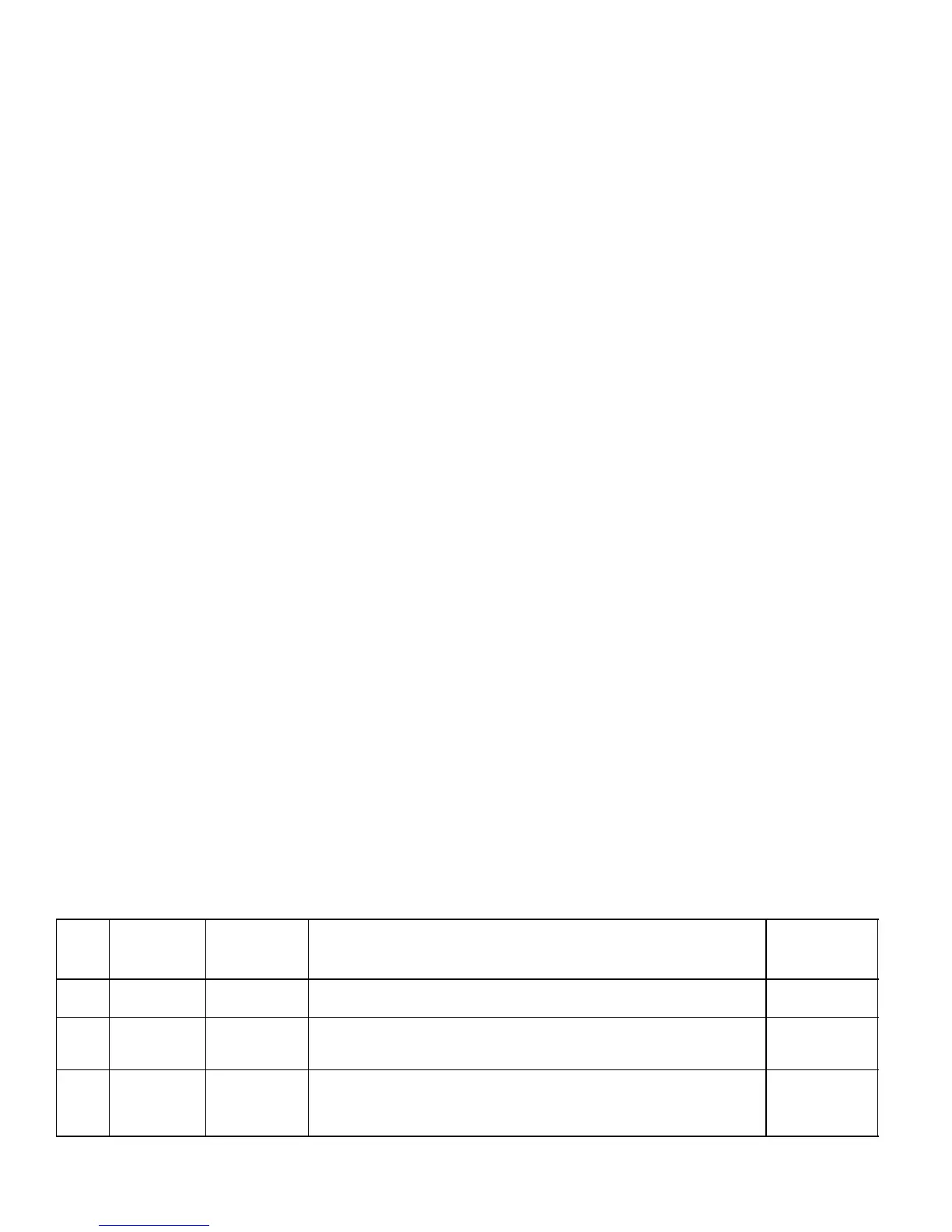
Table 10. Diagnostics Codes
Code
#
(0−off;1−on)
Diag LED
1234
Fault
Indicated
Remedy
Fail-safe
(System
Shut Down)
0 0000 Normal
operation
No remedial action required.
1 1000 Insufficient
cooling
Occurs when there is a call for cooling and the Discharge Air Sensor does
not sense a decrease in supply air temperature indicating the cooling is not
functioning properly.
No
2 0100 Defrost time
> 20 minutes
The defrost board should never allow a defrost for greater than 20 minutes. If
this error occurs, check the outdoor unit to see if it is stuck in defrost mode.
The zone control system will use the backup heat during this error and not
the heat pump.
No
table continued on next page

 Loading...


