GENERAL
Page 9
HARMONY IIIT ZONE CONTROL SYSTEM
Zone Control Panel Jumpers (Determining PIAB Jumper Settings)
Determining PIAB Jumper Settings
NOTE − Use the PIAB Calculation Worksheet on Page 60
(also see example below) to help calculate the zone con-
trol system PIAB settings.
1. From a cooling load analysis, determine what CFM is
required for each zone. Also, from the air handler, de-
termine its minimum and maximum CFM ratings.
2. Using the PIAB formula, found in Table 5 and re-
flected in the worksheet below, calculate the Percent
Into Adjustment Band (PIAB) using the values from
step 1 for each zone. Table 5 also gives example CFM
values to illustrates how to determine the correct
jumper for the PIAB for Zone 1 using those values.
3. Set the air selection jumper for the zone using the per-
cent air determined in step 2. If the percent air falls be-
tween available jumper settings, select the nearest
unit of ten.
4. For each zone, repeat steps 1 through 3.
Note − See page 8 for information on 140F DAS (dis-
charge air sensor) jumper used on Zone 1 PIAB.
Table 5. Determine PIAB jumper setting
example CFM values
Required CFM CFM
Zone 1 Zone 2 Zone 3 Zone 4 Min. Max.
1020 1500 720 OFF 720 2200*
*High cool jumper setting
PIAB formula
100
(Req’d CFM − min. CFM)
(Max. CFM − min. CFM)
x
Using example values above, find PIAB for Zone 1:
PIAB (1020 − 720) = 300 =.20. . . . . . . . . . . . . . . . . . . . . . . . . . . . .
(2220 − 720) =1500. . . . . . . . . . . . . . . . . . . . . . .
PIAB Jumper setting % .20 x 100 20%. . . . . . . . . . . . . . . . . . . .
SETUP TIP!
PIAB calculations should provide a good starting point for
setting jumpers. It may also be beneficial to set jumpers at
a higher percentage of airflow such that the sound of air
rushing is objectionable, and then reduce it incrementally
by 10% until: 1) the sound of air rushing is not objection-
able, and 2) ample, but not excessive, air volume is being
provided to adequately heat or cool the zone.
PIAB Calculation Example (see worksheet on Page 60 )
PIAB = [(Required CFM − Minimum CFM) / (Maximum CFM − Minimum CFM)] * 100
Sample CFM ' Required Minimum Maximum Minimum
Sample PIAB = ([___920 − 450 ] / [ 2000 − 450 ]) x 100
==
bb
Sample PIAB = ([ 470 ] / [ 1550 ]) x 100
=
b
Sample PIAB = [ 0.303 ] x 100 = 30 %
Zone Control Panel Jumpers (Air Reduction)
Continuous Air Reduction Jumpers
During continuous fan mode without either a heating or
cooling demand, the blower runs at the total percentage of
the CFM jumper settings of the zones calling for continu-
ous fan (not to exceed 100% of blower capacity). A contin-
uous air reduction jumper allows the blower speed to be re-
duced by a percentage during continuous fan mode.
The selections are 75%, 50%, 25% and 0%. At the factory,
the jumper is set on 0%. Set the jumper to the position
equal to the amount of continuous air reduction desired.
See figure 9.
NOTE − If the calculations using a reduction percentage
indicated a resulting CFM lower than the blower’s mini-
mum CFM rating, the blower will deliver its minimum CFM
(see figure 6 on Page 8).
Heating Air Reduction Jumpers
NOTE − For heat pump applications, ALWAYS set the
jumper on 0%. High head pressures may result if air is re-
duced during heating mode.
NOTE − For use in warm−climate areas where units have
high cooling capacity with low heat capacity, ALWAYS set
the jumper on 0%.
The heating air reduction jumper enables the blower
speed, during heating only, to run at a reduced rate
compared to the cooling blower speed.
The selections are 40%, 20% and 0%. Jumpers are set to
0% from the factory. Set the jumper to the position equal to
the amount of heating air reduction desired. See figure 9.
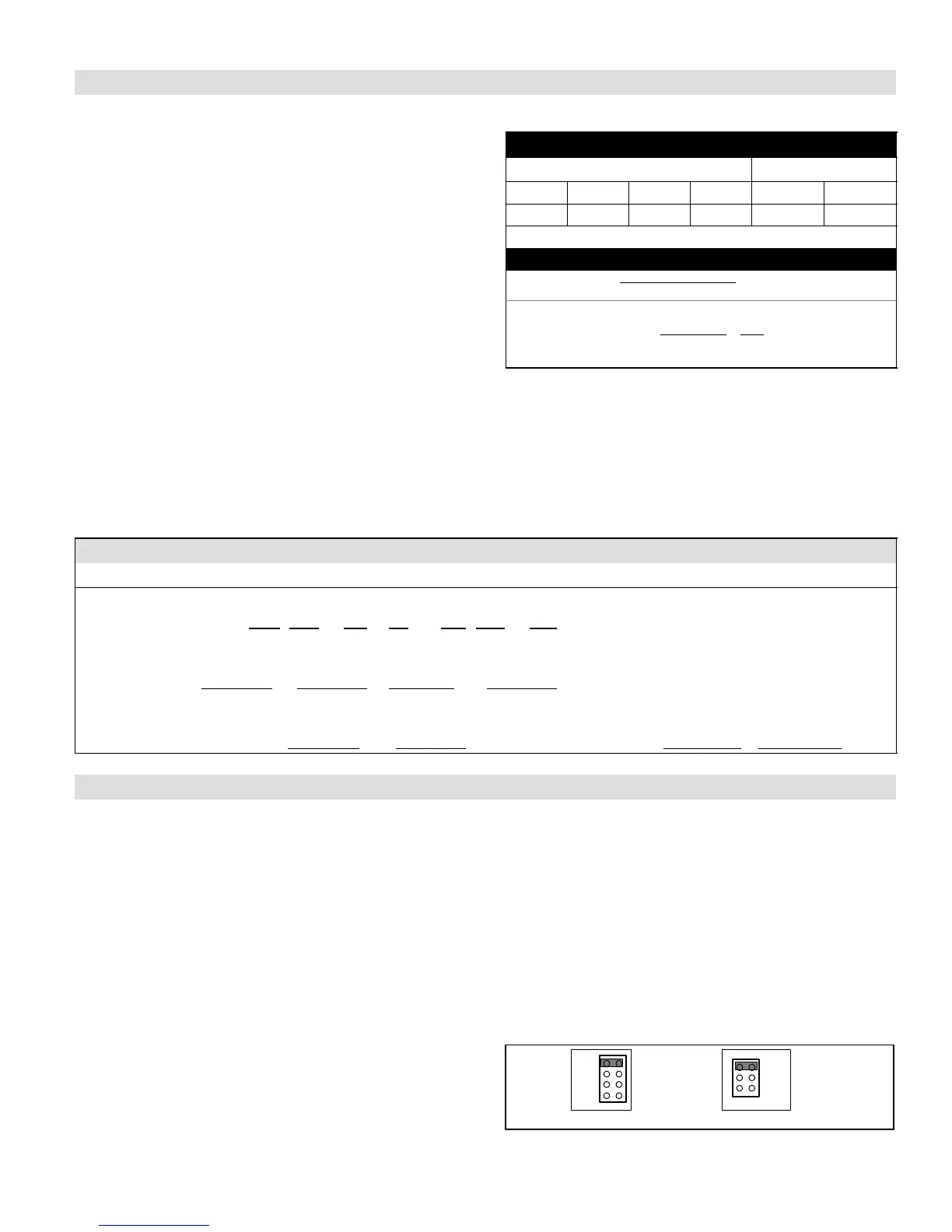
CONTINUOUS HEATING
0%
20%
40%
75%
50%
0%
25%
factory
settings
shown
heating jumper
Must be set on 0%
for heat pump
application
Figure 9. Air Reduction Jumper Settings

 Loading...


