DUAL FUEL
Page 47
HARMONY IIIT ZONE CONTROL SYSTEM
TroubleshootingZoning system with Dual Fuel
- Do dampers respond to demand? 0
volts AC = open. 24 volts AC =
closed. Dampers should drive closed
when 24 volts is jumpered to damper
motor.
- Is wiring correct & in good condition?
- Are thermostats wired correctly?
- Does zone control system respond appropriately to demand?
- Does electronic thermostat have relay switching output? If relay with SCR output is used, not, isola-
tion relays may need to be used.
- 24VAC supplied to each thermostat terminal R from zone control system?
- Check each thermostat for output signal when calling. Heating output W1? Cooling output Y1?
- Error code present?
If so, see trouble-
shooting/diagnostic
section of this
manual (Page 56).
- Are jumpers set correct-
ly for heating and cool-
ing? (Page 11)
- Does outdoor unit respond to demand?
- Is it operating properly?
- Test Defrost. Does outdoor unit initiate and
terminate defrost correctly?
- Check defrost tempering switch, if installed.
- Does zone control system respond
appropriately during defrost?
- Are appropriate outputs energized in
response to demand?
- Does zone control system energize appropriate outputs? During Cooling? During
Heating? During Defrost? During Emer. Heating?
- 24VAC from furnace transformer to R?
- Does indoor unit respond to outputs? Cooling? Heating? Defrost? Emer. Heating?
- Does blower speed change as zone demand changes? If no, does DS output vary
from 0 to 25VDC?
- Line Voltage to transformer?
- 24VAC from transformer to zone control panel?
- Are all wire connections good? Are all wire connections correct?
- Pressure Switch installed. in correct position?
- Does switch open when high pressure condition is simulated (temporarily
blocking airflow in heating mode)?
- Does zone control system respond appropriately when high pressure condi-
tion is simulated (temporarily disconnecting switch simulates high pressure).
- Balance Point Sensor Installed and correctly wired?
- Contacts close on temperature fall?
DAMPERS
System Configuration & E−Heat
jumper settings − page 11.
Heating/cooling
staging jumper
settings − page 10.
Heating
Cooling
120
VAC
24
VAC
THERMOSTATS
- Are PIAB jumpers set cor-
rectly?
- Only 1 jumper per Zone?
(Zone Control System Jump-
er Settings (Page 8) (NOTE:
Zone 1 may have a second
jumper on 140F DAS pins)
- Has 140F DAS jumper been
installed (if required; see
Page 8 & 10)?
- Are continuous & heating air
reduction jumpers set correct-
ly? On heat pumps, Heating
Air Reduction must be 0%.
- Do jumpers provide appropri-
ate speed reduction? If no,
check indoor unit before re-
placing zone control panel.
- Have heating and cooling
staging jumpers been set
for desired 2nd stage op-
eration?
PRESSURE
SWITCH
1 2 3
BALANCE
POINT
SENSOR
140F DAS
jumper pgs
8 & 10.
R
C
Y1
Y2
O
W1
R
G
W1
W2
C
DS
Y1
Y2
HEAT PUMP
VARIABLE
SPEED
FURNACE
PIAB jumper settings − page 8.
DT2 (S89)
Limit Con-
trol (Op-
tional, for
defrost
tempering
kit)
- Is discharge
probe installed?
- Is probe located
in discharge air
plenum as de-
scribed on
Page 6?
- Is it wired cor-
rectly?
DISCHARGE
AIR SENSOR
HUMIDITROL ZONING
ACCESSORY CONTROL
- C" connected
to C"?
- Fuses OK?
TO FURNACE
POWER SUPPLY
- Verify Furnace jumpers/
links cut or removed
(see Pages 28 − 25)
- Verify NO connections
made to Y1 or Y2.
Air
reduction
jumper
settings −
page 9.
ZONE PANEL TRANSFORMER
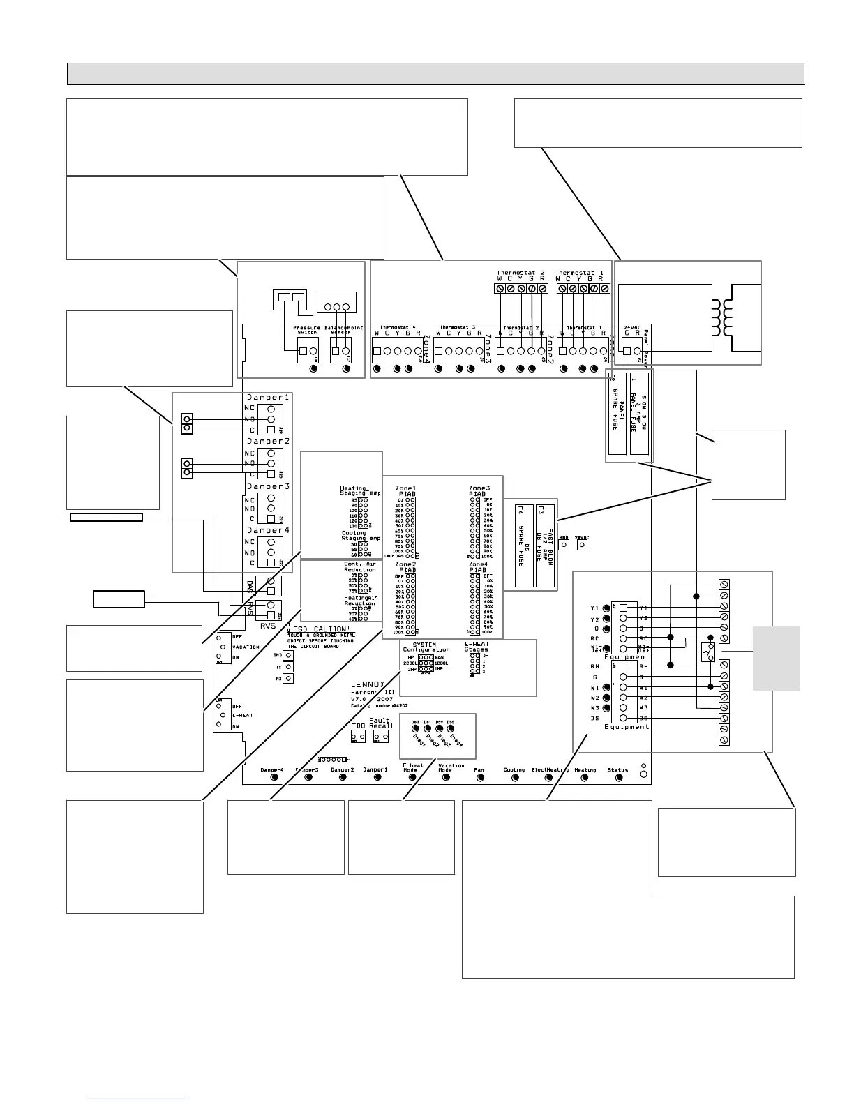
Figure 28. Option 3 − Lennox Heat Pump & Lennox Variable-Speed Gas Furnace (Dual Fuel)

 Loading...


