TROUBLESHOOTING
Page 55
HARMONY IIIT ZONE CONTROL SYSTEM
Fault Recall & Time Delay Override
When the Time Delay Override is pressed and held, the internal clock speeds up by a factor of 60. This overrides the current
time delay and permits the next event to occur. Table 9 identifies the time delays used by the system.
When the Fault Recall button is pressed and released (clicked), the fault codes are displayed (10 most recent). When the
fault recall button is pressed and held, the fault codes are erased. Each code will be displayed for 10 seconds starting with
the most recent code, then the next most recent, and so on. Pressing the button while recalling fault codes will bypass the
10-second timer and go right to the next fault code.
Use the Fault Recall button to observe diagnostic codes that will indicate either correct operation, or help checkout and
troubleshoot problems in the zone control system. Table 10 in the troubleshooting section (see page 56) identifies all diag-
nostic codes.
Press the button once while the system is operating. The system will respond by momentarily lighting all four DIAG LEDs
then displaying the error code, if an error code is stored in memory. This allows a visual check to verify that all four LEDs are
operational before displaying an error code.
Time Delays
Timers used in the Harmony IIIt system define delays which precede or follow a demand, depending on the type of func-
tion. The delays are used to control equipment connected to the system. Table 9 shows how the most noticeable delays are
used.
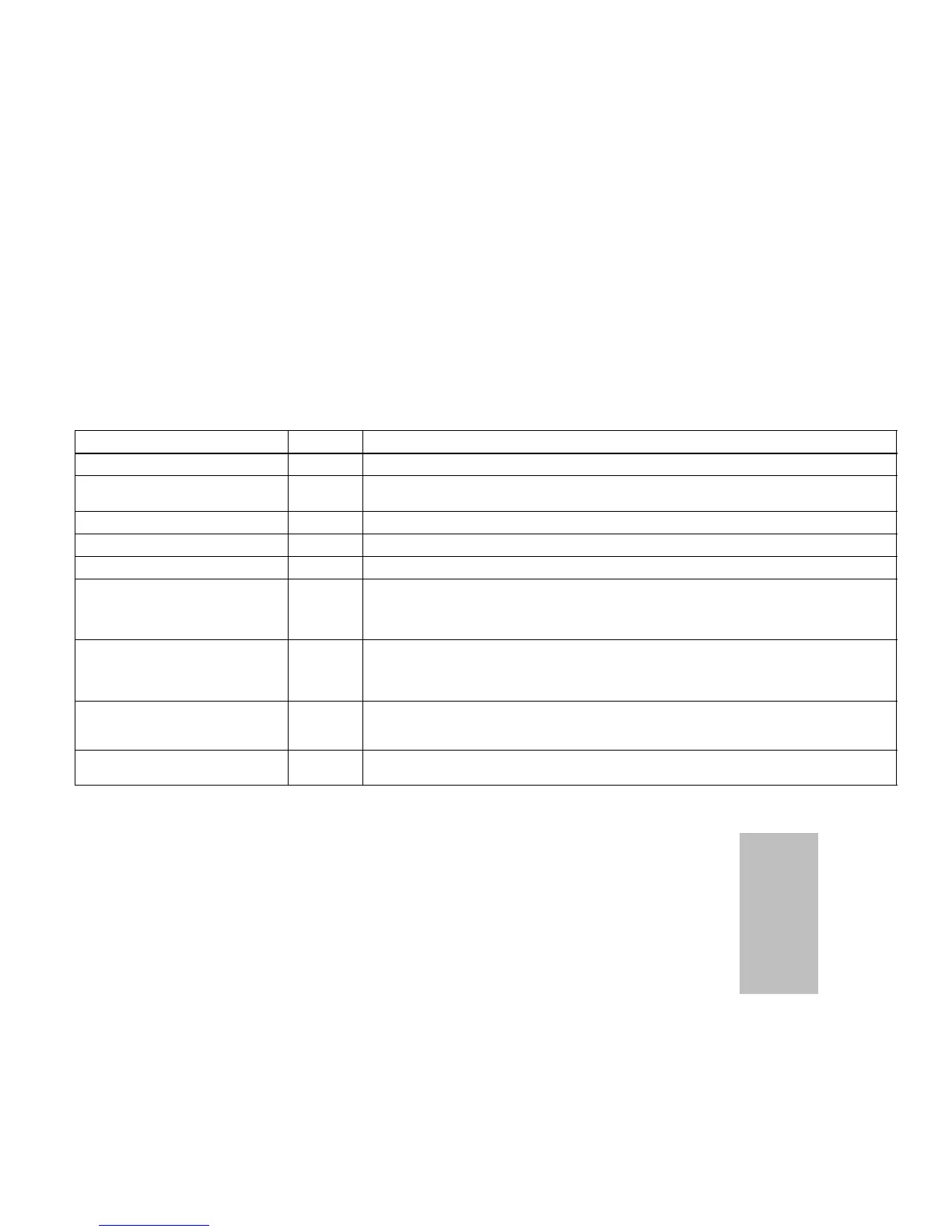
Table 9. Time Delays
Delay Time Function
Blower Off Delay (gas heat only) 3-1/2 min. Gas Furnace only. Delivers air into last zone called during cool down following heat demand.
Compressor Speed Change 4 min. Between low speed and high speed in order to make sure steady state is reached before stag-
ing.
Compressor Off Time 5 min. At end of demand. Equalizes pressure in refrigerant system and prevents short cycling.
Heat Staging (electric) 2 min. Between staging up or down (May stage faster to prevent overshoot/undershoot).
Heat Staging (gas) 3 min. Between staging up or down to achieve steady state.
Dual Fuel Furnace Lock-in Timer 3 hrs. Starts when system enters dual fuel furnace heating when the outdoor temperature is above
balance point. When operating within this 3-hour time, only the furnace is used for heating. Heat
pump will be tried again on the next call after this timer expires. Diagnostic LEDs 2, 3, and 4 will
flash when this timer is active.
Damper Hold 3-1/2 min. This timer is defined as the amount of time to hold the last zone calling open past the thermostat
call drop out. During this time, the panel will not energize the blower (except when a continuous
fan call exists); the controlled equipment will provide this signal. This is a non−adjustable timer
set at 210 seconds.
Autochangeover 20 min. When opposing demands are present, zone control system must work to satisfy current demand
at least 20 min. If current demand is not satisfied after time has elapsed, system will changeover
and satisfy opposing demand. On and Off delays above will also apply.
Dual Fuel Autochangeover 20 min. When temperature is above balance point, heat pump will operate for 20 minutes before allowing
gas furnace to take over heating demand.
Discharge Air Probe Checkout (All Systems)
The discharge air sensor is a temperature-dependent resistor; the higher the temperature, the lower the
resistance. To confirm the sensor is functioning, disconnect both sensor leads from the zone control panel.
Using a digital voltmeter (DVM) set to read resistance, touch the leads from the sensor to the probes of the
DVM.
Do not touch both probes with your fingersdoing so will produce a faulty reading. At 77°F, the resistance
of the sensor will be 10K ohm; at lower probe temperatures, expect higher resistance; at warmer probe
temperatures, expect lower resistance.
After reading the resistance at room temperature, warm the tip of the sensor by holding it in the palm of
your hand, and take another resistance reading. The resistance should be noticeably lower than the pre-
vious readin
.
Temp.
ºF (ºC)
Resistance
(ohms)
65 (18) 13476
70 (21) 11884
75 (24) 10501
80 (27) 9298
85 (29) 8249
90 (32) 7333
The zone control system will monitor the operation of the probe and determine if a failure has occurred. The probe is an integral (but re-
placeable) part of the zone control system. The zone control system will indicate if the probe is operating improperly and needs to be
replaced. The discharge air temperature probe serves several purposes:
1. In cooling systems (and heat pump systems in cooling mode) the probe varies the speed of the compressor from high to low to off
in order to maintain a constant discharge air temperature and prevent coil freezing.
2. In gas heating systems, it is responsible for increasing the speed of the blower to the setting of the CFM jumpers after the discharge
air has warmed up to about 100_F. Also stages equipment up and down to control discharge air temperature.
3. In heat pump systems operating in the heating mode, the probe varies compressor speed and stages of auxiliary heat in order to
maintain a constant discharge air temperature.

 Loading...


