GAS FURNACE
Page 25
HARMONY IIIT ZONE CONTROL SYSTEM
VSM Furnace IFC Electrical Adjustments (G71MPP, SLP98, SL280V, EL296V)
NOTE − Follow all equipment installation instructions provided with each unit.
The variable-speed motor (VSM) in the furnace is controlled by the integrated furnace control (IFC). Adjustment of these
drive controls is made by cutting the clippable on-board links and selecting DIP switch settings. This is described in the
following paragraphs.
The G71MPP, SLP98, SL280V, and EL296V blower motor speed must be adjusted to produce the zoning CFM require-
ments managed by the zone control system.
The Harmony III zone control´s pulse width modulated (PWM) output signal is connected to the DS terminal on the furnace
control. The PWM signal, along with any other thermostat request (G, W1, or W1+W2), controls fan speed linearly between
the minimum and maximum CFM for the furnace as determined by the cool speed DIP switches (see G71MPP & SLP98
Installation Instructions for settings).
Locate the integrated control in the furnace control box area. Before connecting the zone control panel to the integrated
control, complete the applicable electrical adjustments shown in figures 18 or 19.
+
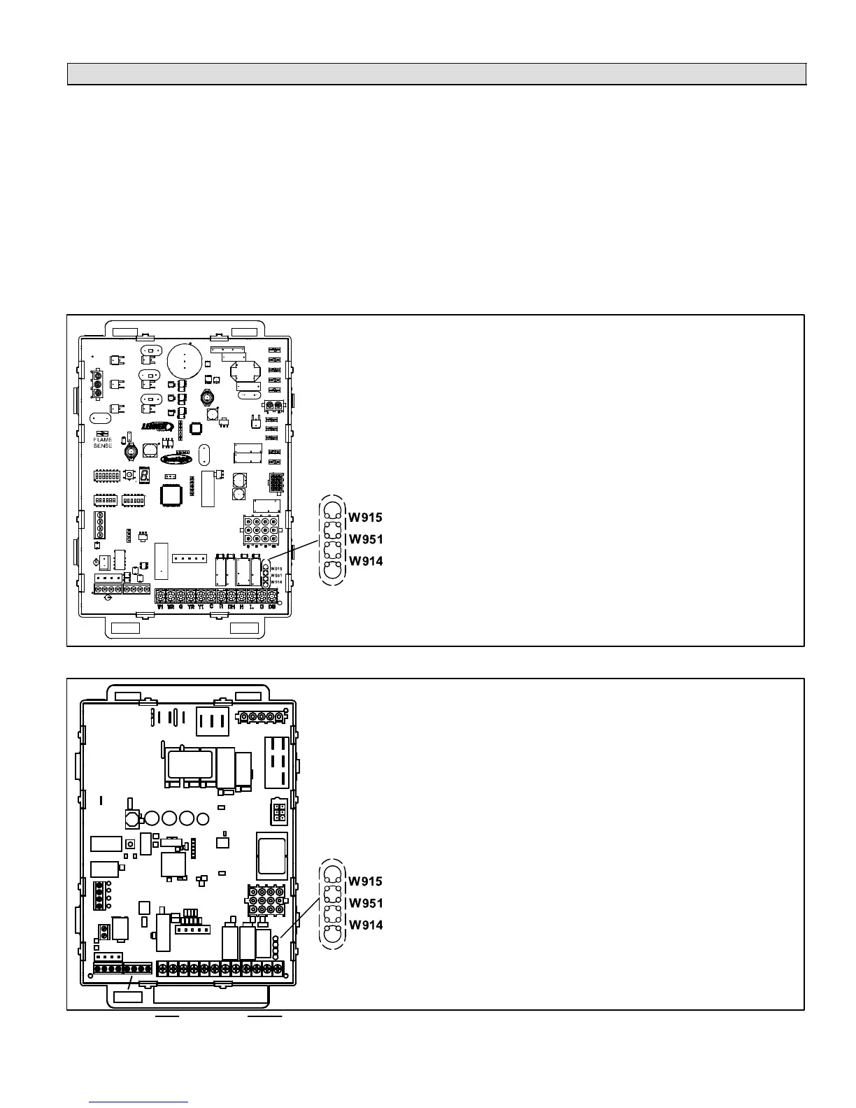
W915 2 Stage Compr (Y1 to Y2)DO NOT CUT
W951 Heat Pump (R to O)DO NOT CUT
W914 Dehum − Harmony (R to DS)CUT IN ALL CASES
EAC
HUM
ON−BOARD LINKS:
Electrical Adjustments
1. In all casescut the clippable on-board link W914 Dehum − Harmony
(between R & DS, see figure 18); if not cut, the zone control panel DS
fuse will blow.
2. DO NOT CUT the clippable on-board link W915 2 Stage Compr (be-
tween Y1 & Y2).
Do NOT cut any wires in the variable speed motor harness.
Figure 18. G71MPP & SLP98 Integrated Furnace Control (IFC) Electrical Adjustments
W915 2 Stage Compr (Y1 to Y2)DO NOT CUT
W951 Heat Pump (R to O)DO NOT CUT
W914 Dehum − Harmony (R to DS)CUT IN ALL CASES
ON−BOARD LINKS:
Electrical Adjustments
1. In all casescut the clippable on-board link W914 Dehum − Harmony
(between R & DS, see figure 18); if not cut, the zone control panel DS
fuse will blow.
2. DO NOT CUT the clippable on-board link W915 2 Stage Compr (be-
tween Y1 & Y2).
Do NOT cut any wires in the variable speed motor harness.
W1W2G
Y2
Y1
CC
RDHL ODS
R
I + I −
CR
I + I −
C
Figure 19. SL280V & EL296V Integrated Furnace Control (IFC) Electrical Adjustments

 Loading...


