HEAT PUMP
Page 16
505023M 08/11
HEAT PUMP
Installing Heat Pump and accessories
Equipment Installation
Follow all equipment installation instructions provided with
each unit.
Pressure Switch
A pressure switch (HFC−22 [27W12]; HFC−410A [27W13])
is required for applications with a Lennox heat pump (Op-
tions 2 and 3). This switch acts as a guard in case of high
head pressures during 1st− and 2nd−stage heating. The
switch’s cut out and cut in points are shown in table 7.
Table 7. Cut−out and Cut−in (Reset) Points
Refrigerant Cut−Out Cut−in (Reset)
HCFC−22 375 psig (2551 kPa) 275 psig (1862 kPa)
HFC−410A 550 psig (3965 kPa) 425 psig (3102 kPa)
NOTE − If a pressure switch is factory installed in the unit,
do not remove the switch or switch wires.
The switch may also be fastened directly to the vapor valve
service port which becomes the discharge line in heat
pump heating mode (see figure 12).
Pressure Switch Wiring
Pull a two−wire thermostat cable from the field-installed
pressure switch to the zone control panel and connect at
the pressure switch, and at the zone control panel as
shown in the connection location diagram (see figure 15).
Tee (High Pressure Switch; Heat Pumps only)
A tee (Lennox #87071) is needed to install the pressure
switch along with a valve core (Schrader) for checking
pressure in the vapor line during heat pump heating mode
(see figure 12).
The switch may also be fastened directly to the vapor valve
service port which becomes the discharge line in heat
pump mode.
TO
REVERSING
VALVE
VAPOR LINE
(TO INDOOR
COIL)
HIGH PRESSURE
SWITCH
NEW SERVICE
PORT
CAUTION − High Pressure Switch must be installed on open side
of tee first to prevent refrigerant loss.
VALVE DEPRES-
SOR TEE (LENNOX
87071)
Figure 12. Tee & Vapor Line High Pressure
Switch
Balance Point Sensor (Outdoor Thermostat)
A balance point sensor (kit 56A87, figure 13) may be imple-
mented in a dual-fuel (Option 3) system. This thermostat
monitors the outdoor temperature, compares it to the bal-
ance point setting, and signals the zone control if the read-
ing is below the set point. The zone control then instructs
the gas furnace to provide all the heating and prohibits the
heat pump from attempting to fill a demand for heat.
Figure 13. Balance Point Sensor (56A87)
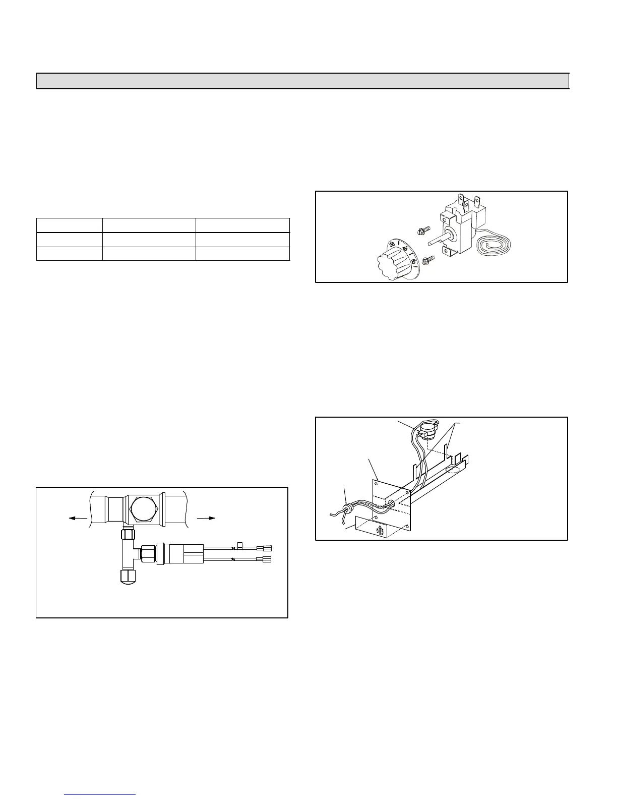
Defrost Tempering Kit
A defrost tempering kit (67M41) may be implemented in a
dual-fuel (Option 3) system. This kit consists of a thermo-
stat probe/switch which is installed between the furnace
and the evaporator coil to turn the furnace on (at 80F) and
off (at 90F) during a defrost cycle. This tempers the dis-
charge air and protects the compressor from high refrig-
eration pressures during defrost. Figure 14 shows the kit;
see figure 3 (Page 6) for location of the probe.
LIMIT CONTROL
MOUNTING
BRACKET
STRAIN
RELIEF
LABEL
WHEN FULLY ASSEMBLED,
TABS ARE BENT DOWN TO
HOLD CONTROL AND WIRES
IN PLACE.
Figure 14. Defrost Tempering Limit Control

 Loading...


