GENERAL
Page 13
HARMONY IIIT ZONE CONTROL SYSTEM
Component Specific Wiring
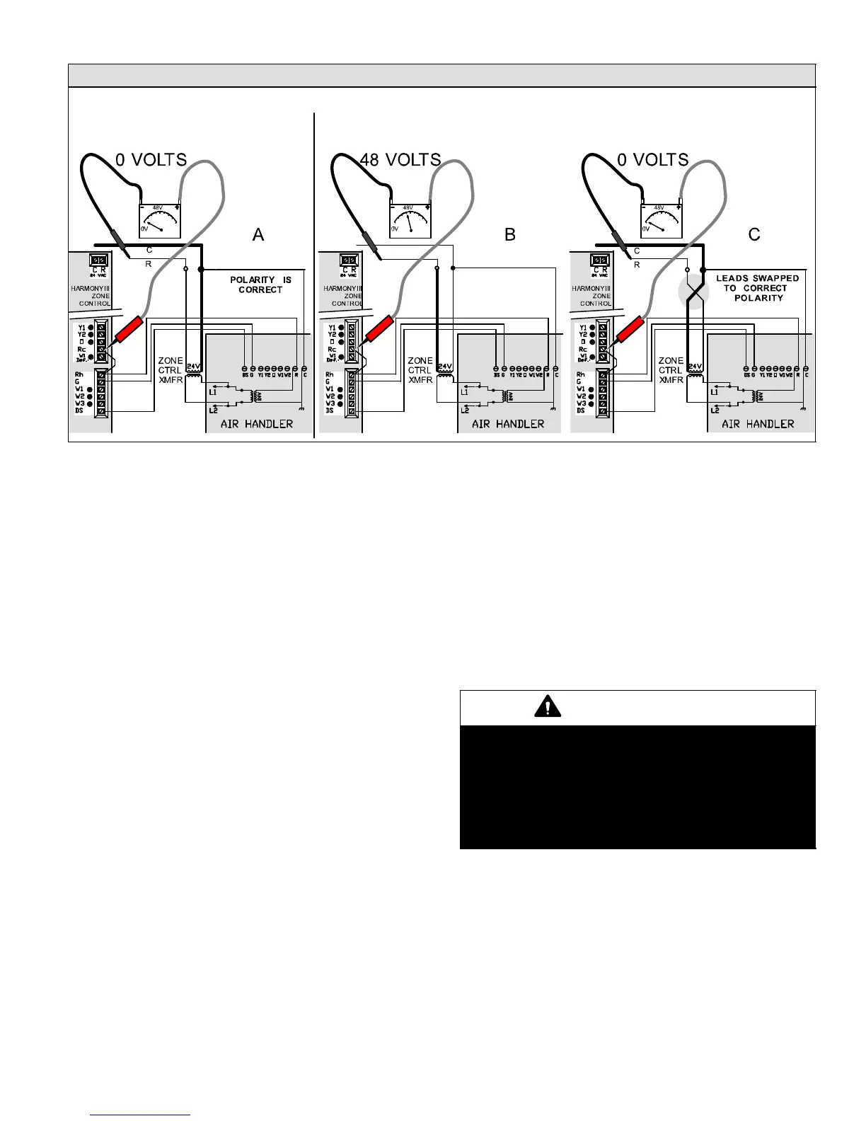
CHECK VOLTAGE BEFORE CONNECTING ZONE CONTROL TRANSFORMER (ZONE CTRL XFMR) LEADS TO THE ZONE CONTROL
PANEL CONNECTIONS
IF METER READS 48 VOLTS (AS SHOWN IN B") THEN POLARITY IS RE-
VERSED; SWAP LEADS (AS SHOWN IN C") AND CONFIRM 0 VOLTS
IF 0 VOLTS (AS SHOWN IN A")
THEN POLARITY IS CORRECT
Figure 11. Confirming Transformer Phasing (polarity) is Correct
Zone Control Transformer Phasing
Using two transformers on a single systemWhen the
Harmony IIIt zone control panel is connected to a system
that has its own transformer, the phasing (or polarity) of the
air handler transformer to the zone control’s add−on trans-
former is extremely IMPORTANT because the zone con-
trol transformer powers the DS" circuit within the zone
control and then connects to the air handler DS" circuit.
The only two transformers that need correct phasing with
their commons connected are the zone control and air han-
dler transformers. Check the phasing prior to connecting
the zone control transformer zone control panel’s connec-
tions. The zone control transformer primary should be the
same source as the air handler to keep it uncomplicated.
Use a 230 volt primary transformer with air handlers
(CBX32MV / CB31MV / CBX40UHV) and use a 115 volt
transformer with furnaces (G61MPV / G71MPP / SLP98 /
SL280V / EL296V) and with CBWMV.
1. Connect the zone control transformer primary to the air han-
dler voltage source (see figure 11).
2. Do not connect the zone control transformer secondary to
the zone control panel at this time.
3. Connect air handler secondary common to the assumed
zone control transformer common.
4. Measure voltage between air handler R" and unconnected
zone control transformer secondary lead (see figure 11):
D if 0 volts (A, figure 11) then polarity is correct; connect the
leads to zone control C and R as shown.
D if 48 volts (B, figure 11) then polarity is reversed; swap
leads as shown and confirm 0 volts (C, figure 11); con-
nect the leads to zone control C and R as shown.
5. With the correct polarity determined, connect C wire to zone
control 24VAC C terminal and R wire to R terminal.
Thermostat Wiring
Using standard electronic 1-heat /1-cool non-heat pump,
non-power robbing thermostats, and five−wire thermostat
cable, wire units as follows:
1. Wire each thermostat to terminals Y, W, G, R, and C.
2. Run cable from each of the thermostats to the zone control
panel. Mark each cable according to the zone thermostat
from where it originates.
3. Strip the cables and attach each of the 5 wires to the zone
control panel (see figures 17 [Page 24], 15 [Page 17], 26
[Page 43]).
Gas Furnace Wiring
IMPORTANT
The common C" terminal of the Harmony IIIt zone
control panel MUST be connected to the common
terminal of the integrated control, or if using a air
handler, MUST be connected to the common termi-
nal of the air handler terminal strip.
If not connected, blower may operate only at the
minimum CFM or will not ramp to zone air volume.
After the furnace is installed, field wire the unit as de-
scribed in the installation instructions provided with the fur-
nace. Use thermostat wire to connect the furnace and the
zone control panel and to connect the zone control panel
24V C" to the integrated control terminal strip C" (see wir-
ing diagram in figure 17).
Condensing Unit Wiring
After the condensing unit is installed, field wire the unit as
shown in the installation instructions provided with the unit.
Use thermostat wire to connect the condensing unit to the
zone control panel (see figure 17).

 Loading...


