AIR HANDLERS
Page 38
505023M 08/11
AIR HANDLERS
Variations on Common Condensing Unit Applications
Heating/Cooling Equipment Installation
Follow all equipment installation instructions provided with
each unit.
Air Handler Wiring
After the air handler unit is installed, field wire the line volt-
age as shown in the installation instructions provided with
the unit. Use thermostat wire to connect the air handler to
the zone control panel (see figure 15) and to connect wire
from zone control panel 24V C" to air handler terminal strip
C".
NOTE − Be sure to remove the factory installed jumper bar
between W1 to W2 and W2 to W3 (CBX40 or CBX32MV
rev 06) or remove the jumper wires between R to W1 and R
to W2 (CBX32MV prior to rev 06).
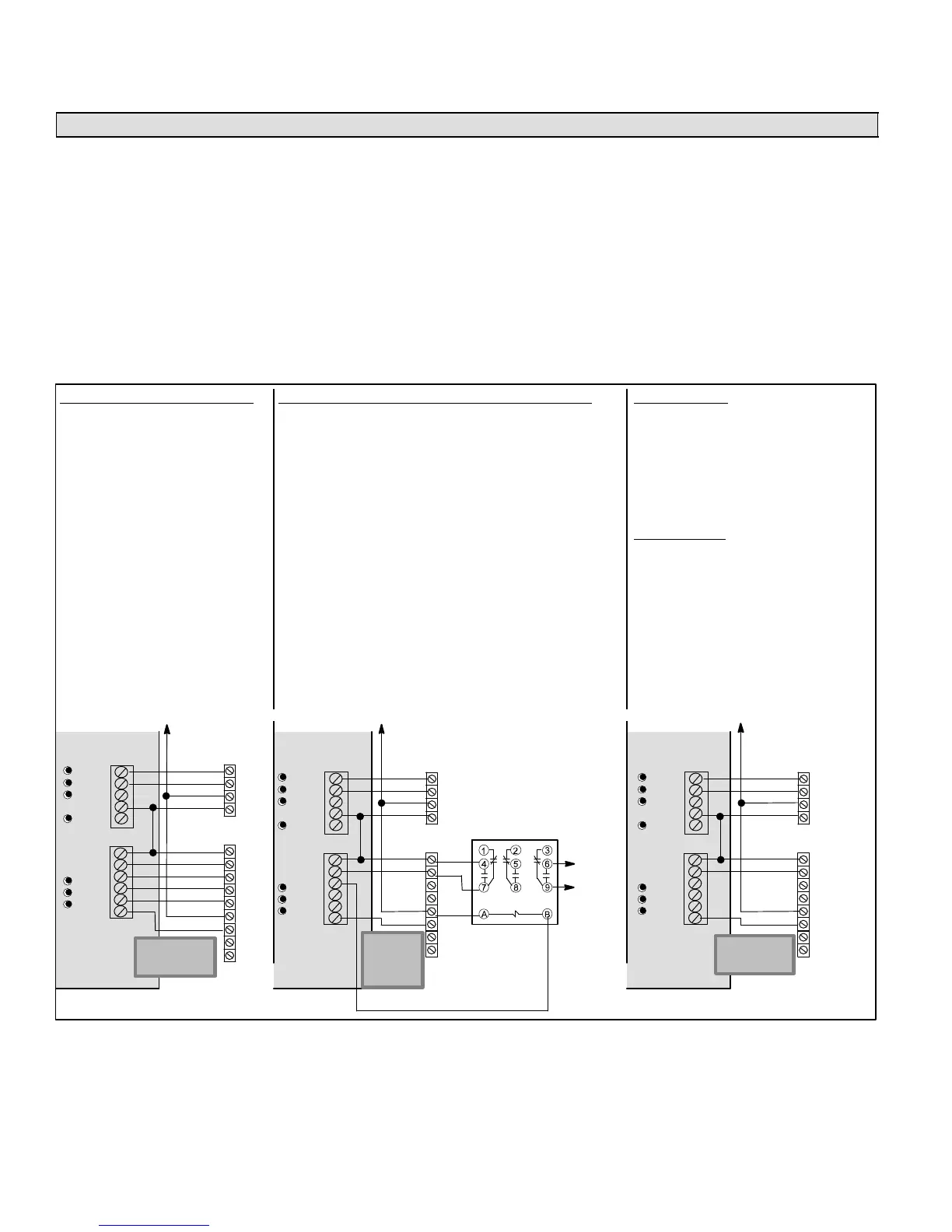
Variations
Several variations may be required for specific applica-
tions. Figure 23 shows alternate wiring and describes spe-
cific jumper configurations and other special modifications
required for each variation. Aside from the variations de-
scribed in figure 23, the connectivity is the same as shown
in figure 17 (Page 24).
Y1
Y2
C
R
R
G
W1
W2
C
DS
Y1
Y2
COOLING ONLY
S System configuration jumpers:
GAS;
1COOL or 2COOL;
Others do not matter.
S As applicable, cut jumpers and harness
wires (see Blower Control Adjustments
− Air Handlers on Page 39).
HEATING ONLY
NOTE − JUMPER between RC and RH
must be in place on the control!
HOT WATER COIL (CBWMV, CBX32MV or CBX40UHV)
S System configuration jumpers:
GAS;
1COOL or 2COOL;
Others do not matter.
S AHC (prior to revision 06): Cut or remove 24 volt jumper Y1
to DS.
S AHC (revision 06): Cut R to DS clippable link on air handler
control.
S CBWMV has no K20 relay, therefore wiring harness modifi-
cation (shown in figure 25, Page 39) is not required.
− Cut or remove 24v jumper Jumper Y1 to DS
− Remove Pink wire from TB1−W1 to J46−2 on CBWMV
NOTE − K212 field hookup relay must be field provided on the
CBX32MV or CBX40.
NOTE − DAS must be located downstream of the cooling coil and
HW coil
COOLING WITH ELECTRIC HEAT
S System configuration jumpers:
HP;
1COOL or 2COOL.
S E−Heat stage jumper set on #
agreeing with # of available heat
stages.
S E−HEAT Selector Switch always
ON.
S As applicable, cut jumpers and
harness wires (see Blower Control
Adjustments − Air Handlers on
Page 39).
Y1
Y2
C
R
R
G
W1
W2
W3
C
DS
Y1
Y2
Y1
Y2
O
RC
W1−Def
RH
G
W1
W2
W3
DS
Equipment
Equipment
Condensing
Unit
VSM Air
Handler
with Elec-
tric Heat
Y1
Y2
C
R
R
G
W1
W2
C
DS
Y1
Y2
Y1
Y2
O
RC
W1−Def
RH
G
W1
W2
W3
DS
Equipment
Equipment
Condensing
Unit
VSM Air
Handler
Y1
Y2
O
RC
W1−Def
RH
G
W1
W2
W3
DS
Equipment
Equipment
Condensing
Unit
CBWMV AND
CBX32MV OR
CBX40UHV USED
WITH HOT WATER
COIL
TO
BOILER
OR
ZONE
CONTROL
K212 FIELD
HOOKUP
RELAY MUST
BE PROVIDED
ON CBX32MV
OR CBX40
VSM
Air
Handler
For any option or variation, connect thermostat wire between C" on terminal strip(s) of controlled equipment and zone control panel 24VAC C" terminal.
IMPORTANT!
DO NOT MAKE
CONNECTIONS
TO Y1 AND Y2
IMPOR-
TANT! DO
NOT MAKE
CONNEC-
TIONS TO
Y1 AND Y2
IMPORTANT!
DO NOT MAKE
CONNECTIONS
TO Y1 AND Y2
Figure 23. Harmony IIIt Zone Control System − Variations on Common Applications

 Loading...


