GAS FURNACE
Page 28
505023M 08/11
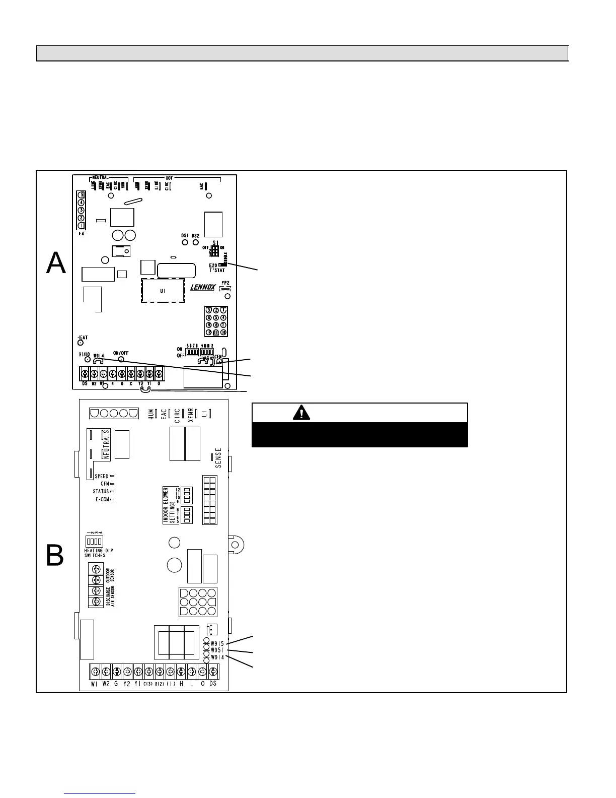
VSM Furnace IFC Electrical Adjustments (G61MPV & G60UHV)
NOTE − Follow all equipment installation instructions provided with each unit.
Variable-speed furnaces are equipped with an integrated furnace control (IFC). The blower motor speed must be adjusted,
by DIP switch setting selection, to produce the cfm required when all the zones are demanding heating or cooling which is
managed by the zone control system.
Locate the integrated control in the furnace control box area. Switch settings on the control affect blower CFM. Before con-
necting the zone control panel to the integrated control, complete the applicable electrical adjustments as shown in figure
20.
Electrical Adjustments
1. In all casescut the clippable on−board link W914 Dehum −
Harmony (between R & DS, shown left).
2. DO NOT CUT clippable on−board link W951 Heat Pump (be-
tween R & O).
3. DO NOT CUT clippable on−board link W915 2 Stage Compr
(between Y1 & Y2).
4. Be sure T’STAT jumper is on TWO".
5. In all casescut and tape wires 2 & 13 on the motor end of
the VSM harness connecting the integrated control to the mo-
tor (see figure 21).
ON−BOARD LINKS:
W951 HEAT PUMPDO NOT CUT
W914 DEHUM − HARMONYCUT IN ALL CASES
W915 2 STAGE COMPRDO NOT CUT
Electrical Adjustments
1. In all casescut the clippable on−board link W914 Dehum −
Harmony (between R & DS, shown left).
2. DO NOT CUT clippable on−board link W951 Heat Pump (be-
tween R & O).
3. DO NOT CUT clippable on−board link W915 2 Stage Compr
(between Y1 & Y2).
4. Be sure to set "T’STAT Heat Stages" to "ON" (2−stage).
5. In all casescut and tape wires 2 & 13 on the motor end of
the VSM harness connecting the integrated control to the mo-
tor (see figure 21).
®
Be sure to cut jumper W914; if not cut,
the zone control panel DS fuse will blow.
IMPORTANT
ON−BOARD LINKS:
W915 2 STAGE COMPRDO NOT CUT
W951 HEAT PUMPDO NOT CUT
W914 DEHUM − HARMONYCUT IN ALL CASES
Figure 20. G61MPV & G60UHV Integrated Furnace Control Electrical Adjustments

 Loading...


