DUAL FUEL
Page 43
HARMONY IIIT ZONE CONTROL SYSTEM
DUAL FUEL
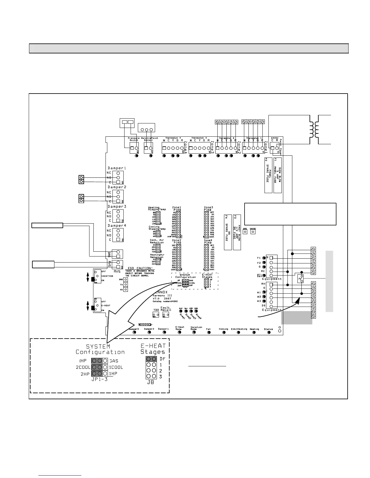
Zone control system wiringDual Fuel Application
Heating/Cooling Equipment Installation
Follow all equipment installation instructions provided with
each unit.
Heat Pump Unit Wiring
After the heat pump unit is installed, field wire the line volta-
ge as shown in the installation instructions provided with
the unit. Use thermostat wire to connect the heat pump to
the zone control panel (see figure 26).
IMPORTANT!
DO NOT MAKE
CONNECTIONS
TO Y1 AND Y2
Thermostat 2 Thermostat 1
W C Y G R W C Y G R
IMPORTANT! Connectivity is NOT COMPLETE until all
electrical adjustments (jumpers and wiring changes) have
been made. See Integrated Control Electrical Adjust-
ments (beginning on Page 28).
BALANCE POINT
SENSOR Kit 56A87
DAMPERS
(Spring open, power close)
PRESSURE SWITCH
21J18 (HFC−22)
27W13 (HFC−410A)
1 2 3
120
VAC
24
VAC
Vacation OFF for individual
zone control.
Vacation ON for all zones to be
conditioned at the same time.
Emergency Heat OFF to allow
Heat Pump to provide heat.
Emergency Heat ON to force
auxiliary (backup) heat to pro-
vide all heating (disallows heat
pump from providing any heat).
R
C
Y1
Y2
O
W1
R
G
W1
W2
C
DS
Y1
Y2
IMPORTANT
Connect
thermostat-gauge
wire to integrated
control C" terminal
HEAT PUMP
VARIABLE
SPEED
FURNACE
NOTE − Do not wire Y" wire(s) from the
Harmony IIIt zone control panel to the
furnace terminal strip. Doing so causes
the motor to search" for proper CFM.
PIAB jumper settings − page 8.
Air reduction
jumper
settings −
page 9.
Heat/cool staging
jumper settings −
page 10.
140F DAS
jumper
pages 8
& 10.
DT2 (S89) Limit Control (Optional
[67M41], for defrost tempering kit)
ON G71MPP & SLP98
Furnace − W2 Not
required, but may
be connected to
increase firing rate.
DISCHARGE AIR SEN-
SOR 88K38 (included)
Connections for REMOTE
VACATION SWITCH OR
Humiditrol
®
Zoning Ac-
cessory
See System Configuration & E−Heat jumper settings − page 11.
SEE IMPORTANT NOTE BELOW!
NOTE: SELECT #
OF HP STAGES
BY PLACING
JUMPER IN
APPROPRIATE
POSITION. (2−STG
HP SHOWN)
CONNECT TO THE
SAME POWER
SUPPLY AS THE
GAS FURNACE
ZONE CONTROL
TRANSFORMER
Figure 26. Harmony IIIt Zone Control System Option 3 −
Lennox Heat Pump & Lennox Variable-Speed Gas Furnace (Dual Fuel)

 Loading...


