GENERAL
Page 6
505023M 08/11
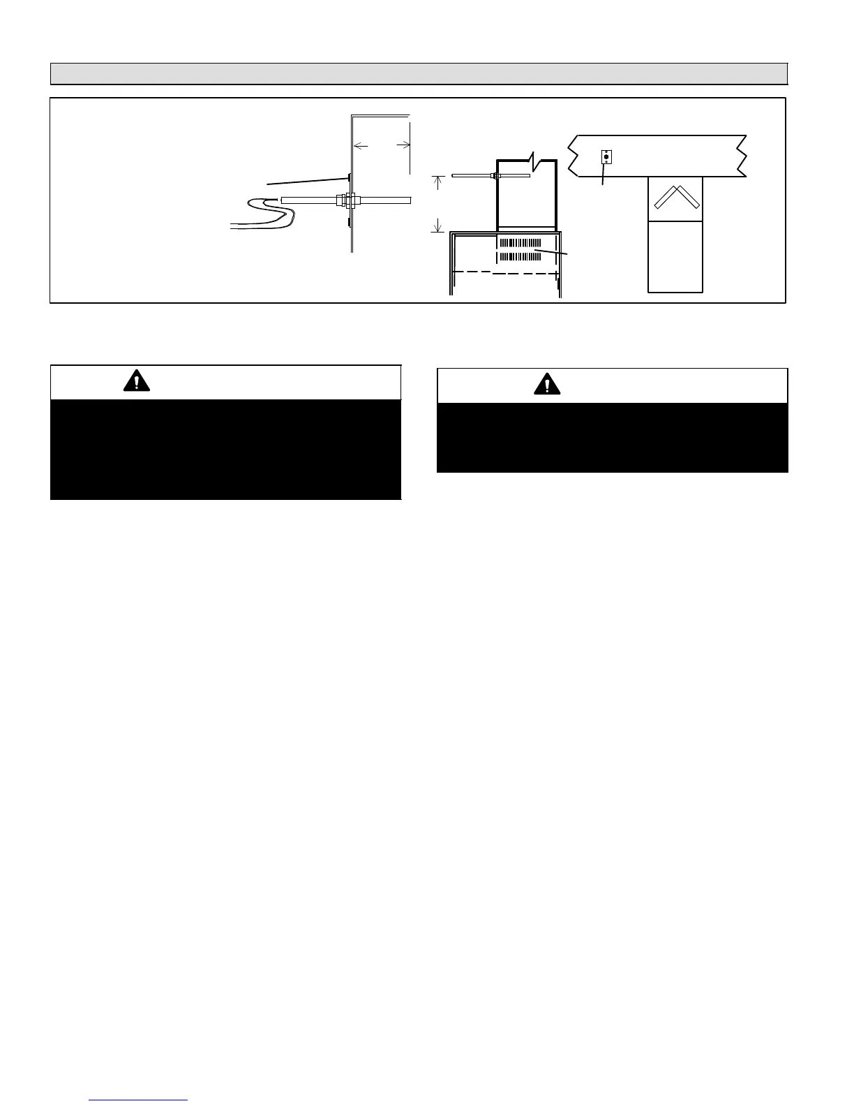
Installing Zone Control Components
plenum
coil
FURNACE
FRONT
VIEW
1/2
the width
of the
plenum
sensor centered in
discharge airflow
(ALSO see note 1)
When possible, position the sensor some dis-
tance away from the coil rather than in the imme-
diate coil area. The Discharge Air Temperature
Sensor should be located at least 10 inches
above the coil.
Fasten the sensor bracket to the plenum
with two self- tapping sheet metal screws.
Connect wires to DAS on zone
control panel, NOT on the AHC or
IFC (see figures 17 through 26).
Be sure that the tip of the sensor is located
approximately 10 inches from the indoor coil in
the discharge plenum, and 1/2 the depth of the
plenum, and centered over the discharge airflow,
side-to-side.
19
(254)
AIR HANDLER
SIDE VIEW
ECB
Electric
Heat
Strips
NOTE 1 − FOR UNITS WITH HUMIDITROLDischarge air sensor
(DAS) MUST be located on the output side of the EDA (if used; see
Humiditrol Zoning Accessory Installation 505,337M)
SENSOR PROBE
see PROBE
MOUNTING
DETAIL below
PLENUM
SENSOR
MOUNTING
DETAIL
Figure 3. Discharge Air Temperature Sensor installation (Typical Upflow Furnace)
Zone Control Panel
IMPORTANT
The electrical power source for the zone control sys-
tem, i.e. the transformer primary, and furnace or air
handler unit must be the same source. In addition,
the zone control system power−up must occur at the
same time or before the furnace or air handler unit
is powered up.
Select an installation site for the Harmony IIIt control con-
sidering the following location parameters:
S Is conveniently accessible and centrally located to facilitate
wiring from thermostats, dampers, pressure switch (if used),
and HVAC equipment.
S Is in a non−condensing area (such as a closet).
S Is NOT in a laundry room (nor other room in the house where
the humidity would typically be much higher than the rest of
the house).
S Is NOT in any part of the building where the temperature may
exceed 150_F.
Discharge Air Sensor
CAUTION
This device is manufactured using unpainted and
pre-painted metal. Sharp sheet metal edges can
cause injury. When installing the device, avoid acci-
dental contact with sharp edges.
Install the discharge air sensor in the discharge plenum
downstream from the cooling coil. Be sure that the dis-
charge air will pass over the sensor before the air is distrib-
uted into the duct system. Typical upflow sensor applica-
tions are shown in figure 3; the sensor dimensions shown
(distance from heat strips, coil, and position in plenum)
also apply to other applications.

 Loading...


