GENERAL
Page 7
HARMONY IIIT ZONE CONTROL SYSTEM
Thermostats
Identify the best location for a thermostat in each zone. If
two or more rooms are within a single zone, place the ther-
mostat in a location that is central to all rooms. For exam-
ple, if a zone contains two bedrooms, try to place the ther-
mostat in a hallway near both bedrooms.
Do not install thermostats in drafty areas, behind doors, in
corners, near radiant heat sources (appliances), near
sunny windows, near concealed pipes and chimneys, nor
in unconditioned spaces such as closets or exterior walls.
Transformer
Obtain an appropriately−rated transformer (see table 1,
Page 4). Install the transformer in either the indoor unit or
in an electrical junction box near the zone control panel.
Dampers
NOTE − The power source for the transformer must be the
same power source as the indoor unit’s transformer.
Motorized dampers in the supply duct system regulate air
to the zones. Some applications will be unique and require
more than one damper per zone. If additional dampers are
required, refer to the the wiring diagram in the Common
System Component Wiring section (page 12). Also, if more
than 6 dampers are used, another transformer and isola-
tion relay will be necessary.
For more effective zone isolation, the return duct system
may also be dampered by zone. Dampers for each zone
must be wired in parallel. Install dampers in the desired
locations; then run thermostat wire from the damper to the
zone control panel and damper relays as needed.
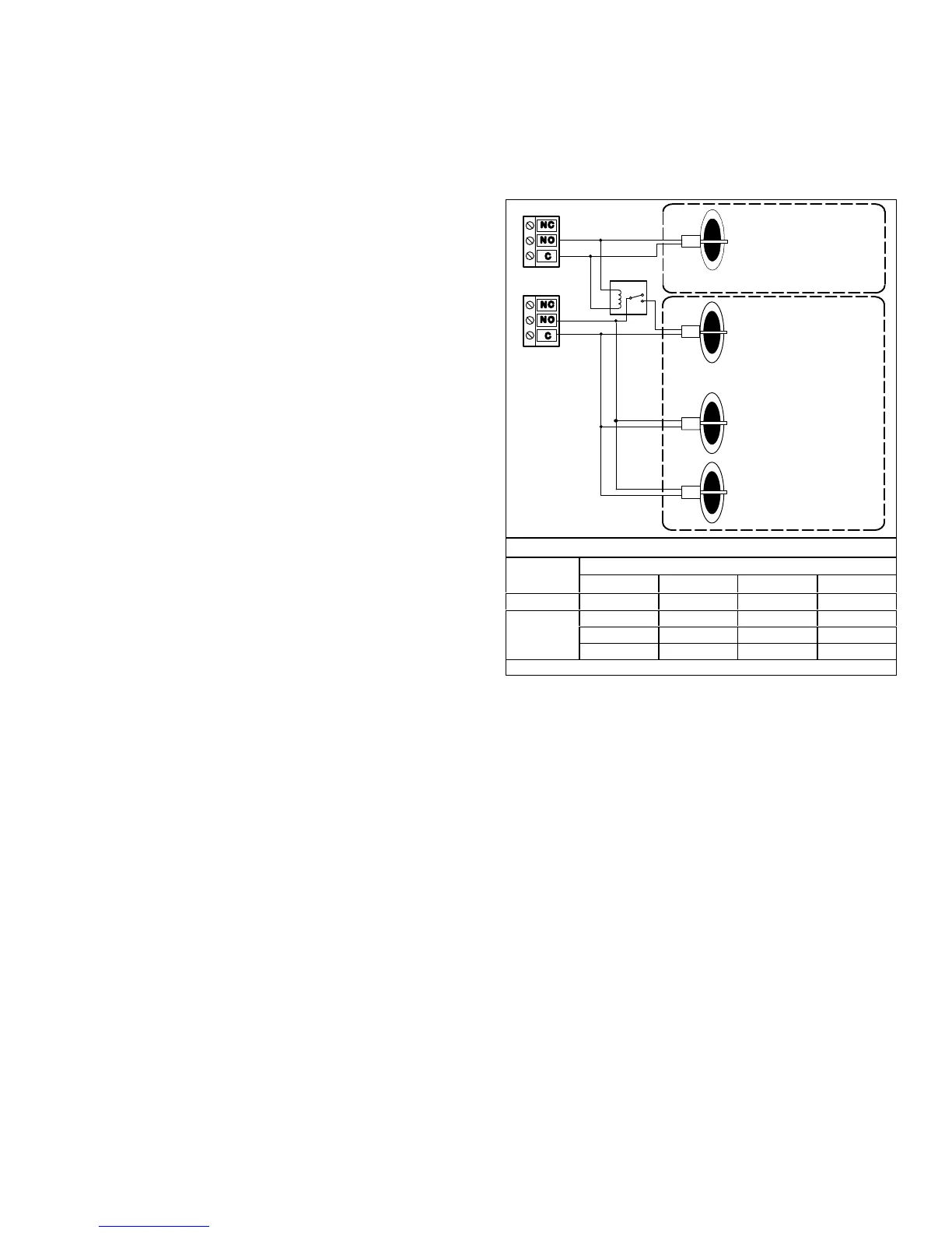
Zone LinkingZone link a small zone to a large zone by
wiring dampers in a manner similar to figure 4. Effectively,
this distributes some of the small zone’s air to another
zone to reduce the chance of overheating or overcooling
the smaller zone. Table 2 (Page 5) shows an example of
an unequal zone and how to adjust to bring it within 25% of
the average CFM. Figure 4 shows how the dampers may
be linked to distribute some of the air from a small zone into
another zone.
Zone 2 (largest zone)
Zone 1 (smallest zone)
This damper is linked to the zone 1
damper; it opens when Zone 1
opens to redirect some air away
from Zone 1 and closes only when
zone 1 damper closes.
RELAY
ZONE 2
DAMPER
DAMPER
DAMPER
All Zone 2
dampers
open only
for calls to
Zone 2
calls for air.
DAMPER
ZONE 1
Note: Zone
Dampers are
Power−Close
type.
Zone Demands to Small and Large Zones
Zone
Dampers
Zone with Demand
None Small Sm.& Lg. Large
Sm.Zone
Closed (24V) Open (0V) Open (0V) Closed (24V)
Lg.Zone
Closed (24V) Open (0V) Open (0V) Open (0V)
Closed (24V) Closed (24V) Open (0V) Open (0V)
Closed (24V) Closed (24V) Open (0V) Open (0V)
Note: Zone Dampers are Power−Close type.
Figure 4. Zone Linking

 Loading...


