HEAT PUMP
Page 18
505023M 08/11
Heat Pump System Start−Up & Checkout
IMPORTANT
The zone control system power−up must occur at the same
time or before the furnace or air handler unit is powered up.
Powering the System (All Systems)
1. Adjust all thermostat settings so that no demand will occur.
2. Apply power to the zone panel transformer and to the air handler and observe the following: all four diagnostic LEDs
will light; then each individual diagnostic LED will light in sequence; then all four diagnostic LEDs will light and extinguish.
3. Finally, the status light will begin to flash, indicating proper operation. Perform heat pump heating checkouts on pages
18 through 19.
Heat Pump Heating Checkout (Single Zone)
Prerequisites:
S
Zone 1 thermostat set to Heat
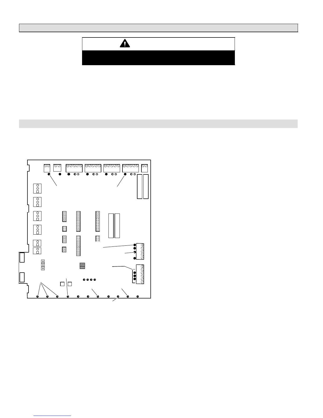
OUTPUT STATUS LEDs
DAMPER 2,3,4 ON
DAMPER 1 OFF
(W) RED ON
PRESSURE
SWITCH LED ON
HEATING ON
FAN ON
ELECTRIC HEATING ON (W/EVENT 3)
EVENT SEQUENCE:
1− Y1 ON
2− Y2 (IF EQUIPPED) ON
IF NO SIGNIFICANT
WARMING AFTER 4 MIN.
3− W1 ON IF NO
SIGNIFICANT WARMING
AFTER 4 MIN; THEN W2;
THEN W3
1. Set zone 1 thermostat for a heat demand; check:
D Zone 1 thermostat W LED on (heating demand).
D Damper LED 1 off (damper open).
D Damper LEDs 2, 3, and 4 on (dampers closed).
D Output Heat Y1 LED on (compressor on).
D Heating LED on.
D Fan LED on.
D Pressure Switch LED on.
The compressor in the outdoor unit begins operating in
the heating mode. At approximately the same time,
the indoor blower starts, operating at a speed accord-
ing to the setting of the PIAB jumper for zone 1. It may
take the blower 60 to 90 seconds to reach this speed.
2. If Single-Stage Heat Pump − Skip to step 3. The dis-
charge air sensor continually samples air tempera-
ture. If, after 4 minutes, air temperature is not warming
significantly, the high speed compressor energizes.
D Output Heat Y2 LED on (high speed compressor).
3. The discharge air sensor continually samples air tem-
perature. If, after (another) 4 minutes, air is not warm-
ing significantly, auxiliary heat sequence begins:
D Electric Heating (E−Heating) LED on.
D Output Heat W1 on, followed by (if available, and if
necessary) W2, and then W3.
4. Remove heat demand from zone 1.
D All LEDs off, except:
D Damper LEDs 2, 3, 4 on.
To check the amount of air being delivered to each
zone and to confirm that each individual zone damper
functions properly, repeat these steps for zones 2 − 4.

 Loading...


