AIR HANDLERS
Page 39
HARMONY IIIT ZONE CONTROL SYSTEM
Air Handler Control Electrical Adjustments (All model VSM Air Handlers)
Electrical AdjustmentsCommunicating CBX32MV (revision 06) and CBX40UHV (all)
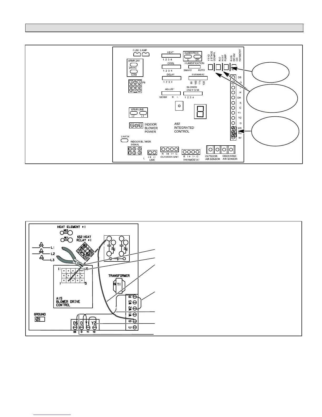
CUT on board
Link R−DS
Remove
W1−W2 and W2−W3
Jumper Bars from the
terminal strip
Electrical Adjustments
As shown in this diagram, make
the following adjustments:
1. Cut on board link R to DS
(Dehum or Harmony).
2. Remove Jumper Bars from
W1 to W2 and W2 to W3.
3. DO NOT CUT on board links
Y1−Y2 2 STAGE COMPR
and R−O HEAT PUMP
DO NOT CUT
on board links
Y1−Y2 2 Stage Compr
and R−0 Heat Pump
Figure 24. Electrical Adjustments for Air Handler Control CBX32MV (revision 06) & CBX40UHV (all)
Electrical AdjustmentsNon−communicating CBX32MV (prior to revision 06), CB31MV and CBWMV
These air handler blower motors are controlled by the BDC3 drive control; CFM adjustment Is by jumper setting selection.
Locate the BDC3 board in the blower control box. Before connecting the zone control panel to the BDC3 board, complete all
of the applicable electrical adjustments as shown in figure 25.
NOTE − Before cutting wires or jumpers, be sure your installation is not affected by Variations on Common Con-
densing Unit Applications" figure 23 (Page 38).
1
4
7
3
6
9
K20 INDOOR
BLOWER RELAY
JP1
BDC3
Electrical Adjustments
As shown in this diagram, make the following adjustments:
In all cases except Cooling Only" or CBWMV units:
1. CUT wire near the BDC3 board JP1 pin 2
2. tape exposed end of short JP1 pin 2 wire
3. re−route wire connected to K20 terminal 4; strip end and
connect to terminal G" (K20 wiring change not required
on CBWMV)
If CBWMV, remove pink wire TB1−W1 to J46−2
Except for Cooling Only" units, remove any jumper(s) be-
tween R − W2 or R − W3
DO NOT CUT jumper R − O
DO NOT CUT Jumper Y1 − Y2
In all cases, CUT Jumper DS − Y1
Figure 25. Electrical Adjustments for Air Handler Control CBX32MV (pre−rev. 06), CB31MV & CBWMV
Set the upper limit of blower CFM as follows:
1. Determine the maximum system CFM requirements (sum of all the individual zones).
2. From the Blower Motor Performance table in the unit’s installation instructions, determine the COOL Speed jumper
setting that corresponds to this CFM; then set the COOL Speed jumper setting on the BDC3 board to this value.
For more information on setting blower speed, refer to section on Blower Speed and Adjustment" in the blower unit’s instal-
lation instructions.

 Loading...


