DUAL FUEL
Page 45
HARMONY IIIT ZONE CONTROL SYSTEM
Dual Fuel Gas Heating Checkout (Multiple Zone)
Prerequisites:
S
All zone thermostats set to Heat.
S Balance Point Sensor set at higher temperature than outdoor
BPS-sensed temperature (red balance point sensor LED
on).
OR
S Balance Point Sensor inputs jumpered to simulate cold out-
door temperature below balance point (red balance point
sensor LED on).
OUTPUT STATUS LEDs
DAMPER 2,3,4 OFF
W1 ON
(W) RED ON
HEATING ON
FAN ON
1. Set all zone thermostats for a heat demand; check for
the following:
D All zone thermostat W LEDs on (heat demands).
D LEDs dampers 1 − 4 off (all dampers open).
D Output Heat W1 LED on (furnace on).
D Heating LED on.
The furnace begins ignition sequence after a heat de-
mand is detected. The zone control system will start
the furnace blower on low speed (0 PIAB) 45 seconds
after the combustion cycle has begun.
2. When 100ºF warm air is sensed by the discharge air
sensor, the fan LED comes on and the blower will
slowly increase to speed required by the zones calling.
The blower operates at a speed equivalent to the sum
of all zone PIAB jumpers but at a maximum not to ex-
ceed the setting of the heating air reduction jumper. It
may take the blower 60 to 90 seconds to reach this
speed.
3. Set all zone thermostats for NO heat demands; check:
D Output Heat W1 LED off.
D Heating LED off.
D Fan LED off (blower turns off after delay).
D All zone thermostat W LEDs off.
D DamperLEDs − Last zone thermostat demand re-
moved: LED is off (this zone’s damper remains
open during 3−1/2 minutepurge); other zones
damper LEDs are on during the 3−1/2 minute
purge (dampers closed). After 3−1/2 minute delay,
all dampers LEDs go off (dampers open).
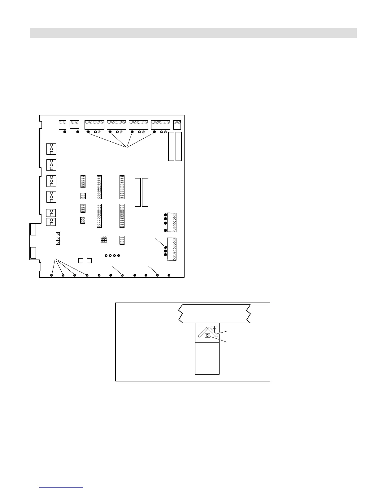
Defrost Tempering (Kit 67M41)
plenum
coil
furnace
front
defrost tempering
sensor/limit con-
trol (if used in
Option 3)
Install the defrost tem-
pering sensor (if used)
where shown. (See
504,797M installation in-
structions.)
Typical Upflow
Furnace Shown
Figure 27. Defrost Tempering Sensor Placement

 Loading...


