HEAT PUMP
Page 21
HARMONY IIIT ZONE CONTROL SYSTEM
TroubleshootingZoning system with Heat Pump
- Do dampers respond to demand? 0
volts AC = open. 24 volts AC =
closed. Dampers should drive closed
when 24 volts is jumpered to damper
motor.
- Is wiring correct & in good condition?
- Are thermostats wired correctly?
- Does zone control system respond appropriately to demand?
- Does electronic thermostat have relay switching output? If relay with SCR output is used, not, isola-
tion relays may need to be used.
- 24VAC supplied to each thermostat terminal R from zone control system?
- Check each thermostat for output signal when calling. Heating output W1? Cooling output Y1?
- Error code present?
If so, see trouble-
shooting/diagnostic
section of this
manual (Page 56).
- Are jumpers set cor-
rectly for auxiliary
heat and cooling?
(Page 11)
- Is discharge
probe installed?
- Is probe located
in discharge air
plenum as de-
scribed on
Page 6?
- Is it wired cor-
rectly?
- Does outdoor unit respond to demand?
- Is it operating properly?
- Test Defrost. Does outdoor unit initiate and
terminate defrost correctly?
- W1 energized during defrost?
- Does zone control system respond appropri-
ately during defrost?
- Are appropriate outputs energized in re-
sponse to demand?
- Does zone control system energize ap-
propriate outputs? During Cooling? During
Heating? During Defrost? During Emer.
Heating?
- 24VAC from furnace transformer to R?
- Does indoor unit respond to outputs? Cool-
ing? Heating? Defrost? Emer. Heating?
- Does blower speed change as zone de-
mand changes? If no, does DS output vary
from 0 to 25VDC?
- Line Voltage to transformer?
- 24VAC from transformer to zone control panel?
- Are all wire connections good? Are all wire connections correct?
- Pressure Switch installed in correct position?
- Does switch open when high pressure condition is simulated (tem-
porarily blocking airflow in heating mode)?
- Does zone control system respond appropriately when high pres-
sure condition is simulated (temporarily disconnecting switch
simulates high pressure).
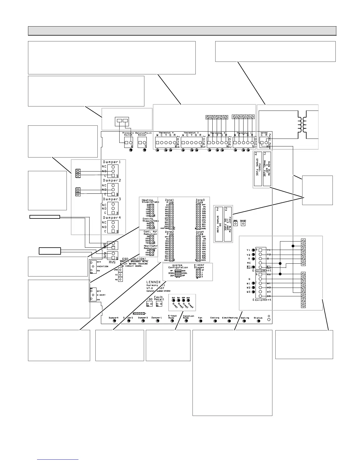
DAMPERS
System Configuration & E−Heat
jumper settings − page 11.
PIAB jumper settings − page 8.
Heating/cooling
staging jumper
settings − page 10.
240
VAC
24
VAC
Thermostat 2 Thermostat 1
W C Y G R
DISCHARGE
AIR SENSOR
THERMOSTATS
- Are PIAB jumpers set correctly?
- Only 1 jumper per Zone? (Zone
Control System Jumper Settings
[Page 8])
- Are continuous & heating air re-
duction jumpers set correctly?
On heat pumps, Heating Air
Reduction must be 0%.
- Do jumpers provide appropriate
speed reduction? If no, check
indoor unit before replacing
zone control panel.
- Have heating and cooling
staging jumpers been set for
desired 2nd stage operation?
PRESSURE
SWITCH
R
C
Y1
Y2
O
W1
R
G
W1
W2
C
DS
Y1
Y2
HEAT PUMP
VARIABLE
SPEED AIR
HANDLER
W C Y G R
HUMIDITROL ZONING
ACCESSORY CONTROL
- Verify Air Handler
jumpers/links cut or re-
moved (see Page 39)
- Verify NO connections
made to Y1 or Y2.
- C" connected
to C"?
- Fuses OK?
Air reduction
jumper
settings −
page 9.
ZONE PANEL TRANSFORMER
TO AIR HANDLER
POWER SUPPLY
Figure 16. Lennox Heat Pump & Lennox Variable-Speed Air Handler

 Loading...


