GAS FURNACE
Page 35
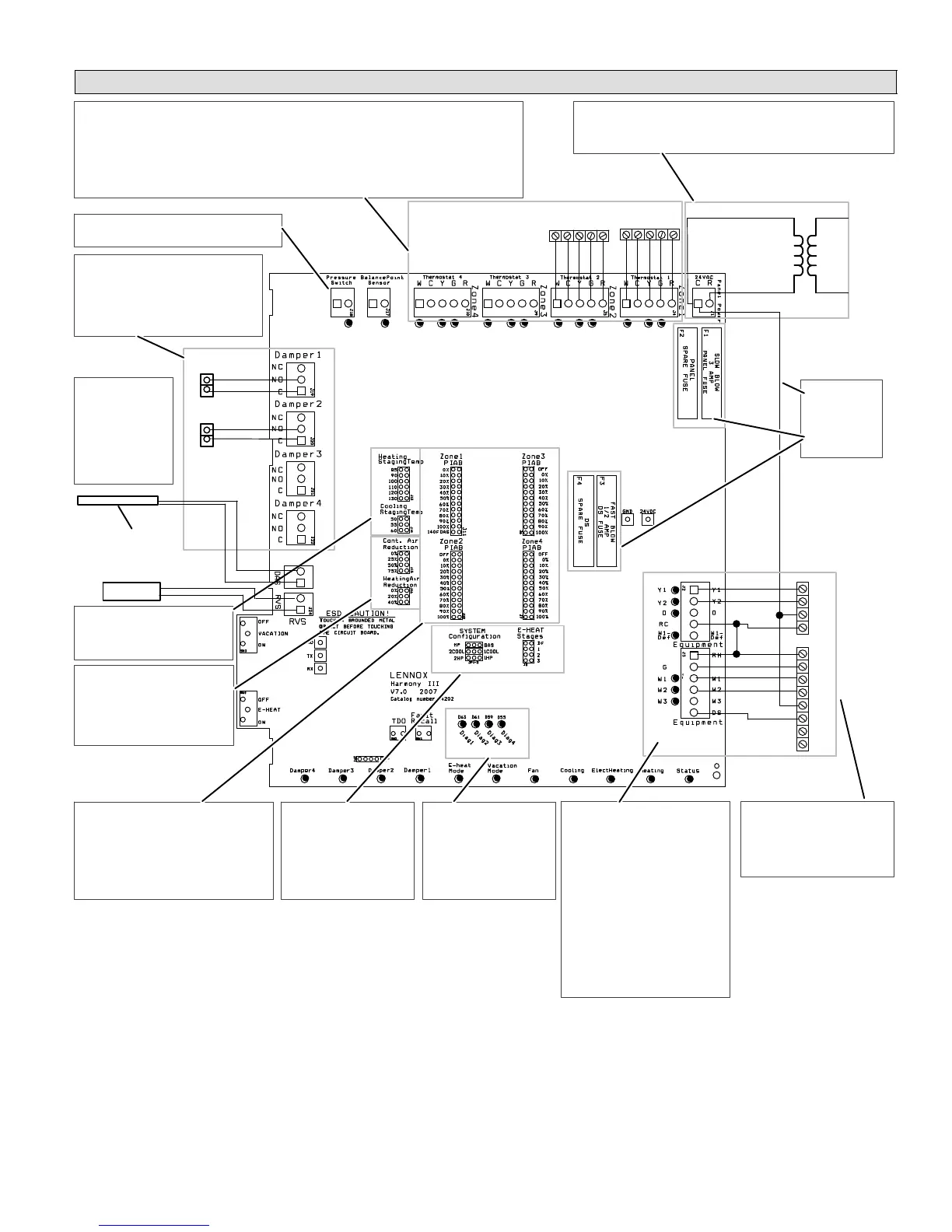
HARMONY IIIT ZONE CONTROL SYSTEM
Troubleshooting DiagramZone system with Gas Furnace
- Do dampers respond to demand? 0
volts AC = open. 24 volts AC =
closed. Dampers should drive closed
when 24 volts is jumpered to damper
motor.
- Is wiring correct & in good condition?
- Are thermostats wired correctly?
- Does zone control system respond appropriately to demand?
- Heat/cool thermostat used? (Must not use heat pump thermostat.)
- Does electronic thermostat have relay switching output? If not, isolation relays may need to be used.
- 24VAC supplied to each thermostat terminal R from zone control system?
- Check each thermostat for output signal when calling. Heating output? Cooling output?
- C" connected
to C"?
- Fuses OK?
- Error code present? If
so, see troubleshooting/
diagnostic section of this
manual (Page 56).
- Are jumpers set cor-
rectly for furnace and
cooling? (Page 11)
- Is discharge
probe installed?
- Is probe located
in discharge air
plenum as de-
scribed on
Page 6?
- Is it wired cor-
rectly?
- Does outdoor unit respond to
demand?
- Is it operating properly?
- Are appropriate outputs ener-
gized in response to demand?
- Does zone control system en-
ergize appropriate outputs?
During Cooling? During Heat-
ing?
- 24VAC from furnace transform-
er to R?
- Does furnace respond to out-
puts?
- Does blower speed change as
zone demand changes? If no,
does DS output vary from 0 to
25VDC?
- Line Voltage to transformer?
- 24VAC from transformer to zone control panel?
- Are all wire connections good? Are all wire connections correct?
- (No pressure Switch should be installed.)
DAMPERS
System Configuration & E−Heat
jumper settings − page 11.
PIAB jumper settings − page 8.
Heating/cooling
staging jumper
settings − page 10.
120
VAC
24
VAC
Thermostat 2 Thermostat 1
W C Y G R
DISCHARGE
AIR SENSOR
THERMOSTATS
Y1
Y2
C
R
R
G
W1
W2
C
DS
Y1
Y2
VARIABLE SPEED
FURNACE
2-STAGE
CONDENSING
UNIT
- Are PIAB jumpers set correctly?
- Only 1 jumper per Zone? (Zone Control
System Jumper Settings (Page 8)
(NOTE: Zone 1 may have a second
jumper on 140F DAS pins)
- Has 140F DAS jumper been installed (if
required; see Page 8 & 10)?
- Are continuous & heating air re-
duction jumpers set correctly?
- Do jumpers provide appropriate
speed reduction? If no, check
indoor unit before replacing
zone control panel.
- Have heating and cooling
staging jumpers been set for
desired 2nd stage operation?
140F DAS
jumper
pages 8
& 10.
W C Y G R
HUMIDITROL ZONING
ACCESSORY CONTROL
ZONE PANEL TRANSFORMER
- Verify Furnace jump-
ers/links cut or re-
moved (see Pages 28 −
25) Page 39)
- Verify NO connections
made to Y1 or Y2.
Air reduction
jumper
settings −
page 9.
TO FURNACE
POWER SUPPLY
Figure 22. Option 1 − Lennox Variable-Speed Gas Furnace and Lennox Condensing Unit

 Loading...


