MX-FR Series Modular Matrix Frames – User's Manual 118
Port Status Commands
Input Port Status
Shows the actual status of the input ports. The response length changes according to the frame size. The
meaning of the values changes according to the input board types, as the boards have different functions
and capabilities.
Command and Response
ȩ {:ISD}
Ȩ (ISD•<input_d>)CrLf
Parameters
<input_d> may contain 9, 17, 33 or 80 hexadecimal numbers. Each number represents the state of the
corresponding input port. The meaning of the responded number depends on the actual board (port) type.
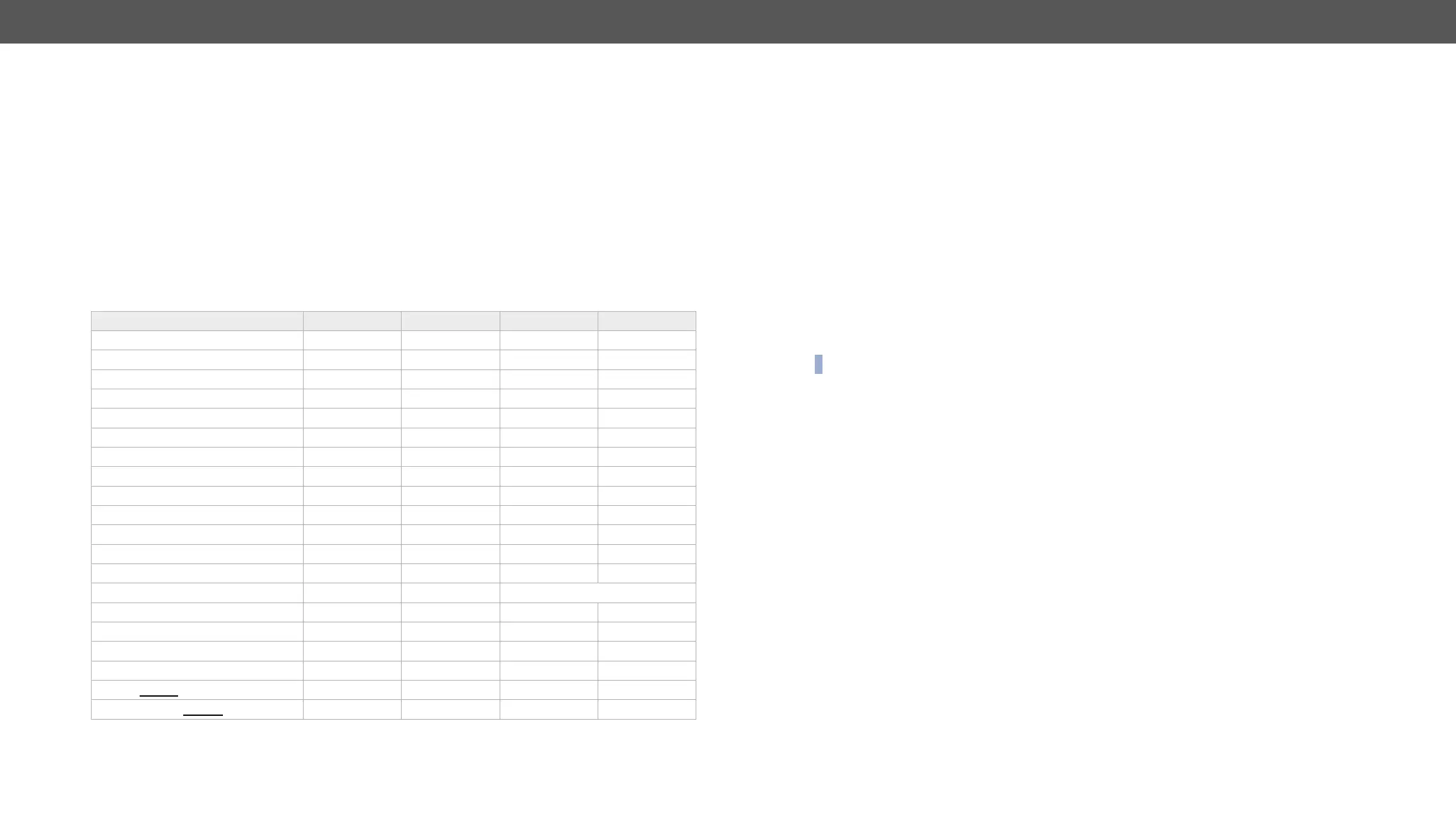
The binary representation of the responded hexadecimal numbers is shown below.
Board Type 3. bit (MSB) 2. bit 1. bit 0. bit (LSB)
MX-DVID-IB 0 0 0 clock detect
MX-DVI-TP-IB 0 0 0 clock detect
MX-DVI-TP-IB+ 0 0 0 clock detect
MX-DVI-OPT-IB 0 0 0 laser + clock
MX-DVIDL-IB 0 0 0 clock detect
MX-DVIDL-OPT-IB 0 0 0 laser + clock
0 HDMI mode signal detect source 5V
0 HDMI mode signal detect source 5V
0 HDMI mode signal detect source 5V
0 HDMI mode signal detect source 5V
HDCP active HDMI mode TX detect clock detect
analog signal HDCP active digital signal source 5V
MXD-UMX-IB analog signal HDCP active digital signal source 5V
MX-3GSDI-IB video detect audio detect type: 01=SD, 10=HD, 11=3G
HDCP active HDMI mode clock detect source 5V
HDCP active HDMI mode clock detect source 5V
MX-TPS-IB, -S, -A HDCP active HDMI mode clock detect TPS link pres.
MX-TPS2-IB-P, -AP, -SP HDCP active HDMI mode clock detect TPS link pres.
MX-4TPS2-IB, -A, -S HDCP active HDMI mode clock detect TPS link pres.
MX-4TPS2--IB, -A, -S HDCP active HDMI mode clock detect source 5V
▪ Source 5V: The connected source sends 5V.
▪ Clock detect: TMDS clock is present.
▪ Laser + Clock: Laser detected and TMDS clock is present.
▪ Signal Detect: Video signal is present (TMDS stream can be recognized).
▪ HDMI mode: The incoming signal is HDMI.
▪ HDCP active: The incoming signal is encrypted.
▪ TX detect: Communication with optical transmitter is OK.
▪ Analog signal: Video signal is present on the analog input.
▪ Digital signal: Video signal is present on the digital input.
Example #hdcp
ȩ {:isd}
Ȩ (ISD 113337770011000000000000000000007)CrLf
DVI signals and Inputs 6-8 have HDMI signals. The second input board is a DVI board. Input 11 and 12 have
DVI signals. The Test Input port has an HDMI signal.
INFO: Both Clock Detect and Signal Detect can be used to check if there is an incoming signal.
 Loading...