3. Product Overview MX-FR Series Modular Matrix Frames – User's Manual 33
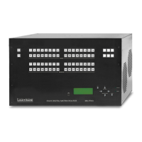
Ethernet Ports
Lightware matrix routers can be remote controlled through Ethernet as well. The
Ethernet port can be connected to a LAN hub, switch or router with a UTP patch
cable. If connecting to a computer directly, a cross UTP cable has to be used! The
robust Neutrik EtherCON connector ensures reliable connection, however, normal
ATTENTION!
allowed to be connected to the Ethernet connector! It seriously damages both
devices.
TPS and TPS2 I/O Boards
two LEDs and it has the same pin connection as the Neutrik EtherCON.
Further Connectors
RS-232 Ports
MXD-HDMI-TP interface boards provide standard 9-pin female and
male D-sub receptacles for serial port pass-through to remote HDMI-TP
extenders. The MX-CPU2 boards also contain an RS-232 port, which
allows to remote control the matrix via industry standard 9-pole D-sub
female connector. #rs-232 #rs232 #serial
ATTENTION! The pinouts of the two connectors are different, which is highlighted in table below.
Pin
1 not connected not connected
2 RX data receive TX data transmit
3 TX data transmit RX data receive
4 DTR (connected to Pin 6) DTR (connected to Pin 6)
5 GND signal ground (shield) GND signal ground (shield)
6 DSR (connected to Pin 4) DSR (connected to Pin 4)
7 RTS (connected to Pin 8) RTS (connected to Pin 8)
8 CTS (connected to Pin 7) CTS (connected to Pin 7)
9 not connected not connected
LED1, Amber LED2, Green
OFF 10 Mbps No link
Blinking Activity
ON 100 Mbps Link is active
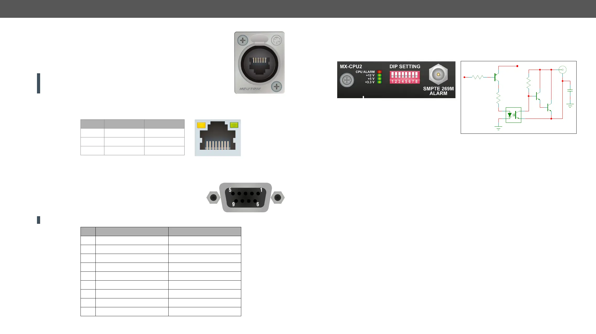
Alarm Output
BNC output connector for SMPTE 269M alarm signaling. The router handles different error levels. Only the
three highest level errors trigger the alarm output and the CPU alarm LED, see more information in the Error
Handling section.
 Loading...