MX-FR Series Modular Matrix Frames – User's Manual 137
Setting the Parameters
Command and Response
ȩ {:AUDSRC#<in>@I=<aud_mode>}
Ȩ (AUDSRC#9@SI=<aud_mode>;)CrLf
Example
ȩ {:AUDSRC#9@SI=B}
Ȩ (AUDSRC#9@SI=B;)CrLf
The new setting is in the response; see the Parameters for the details.
Parameters #audio
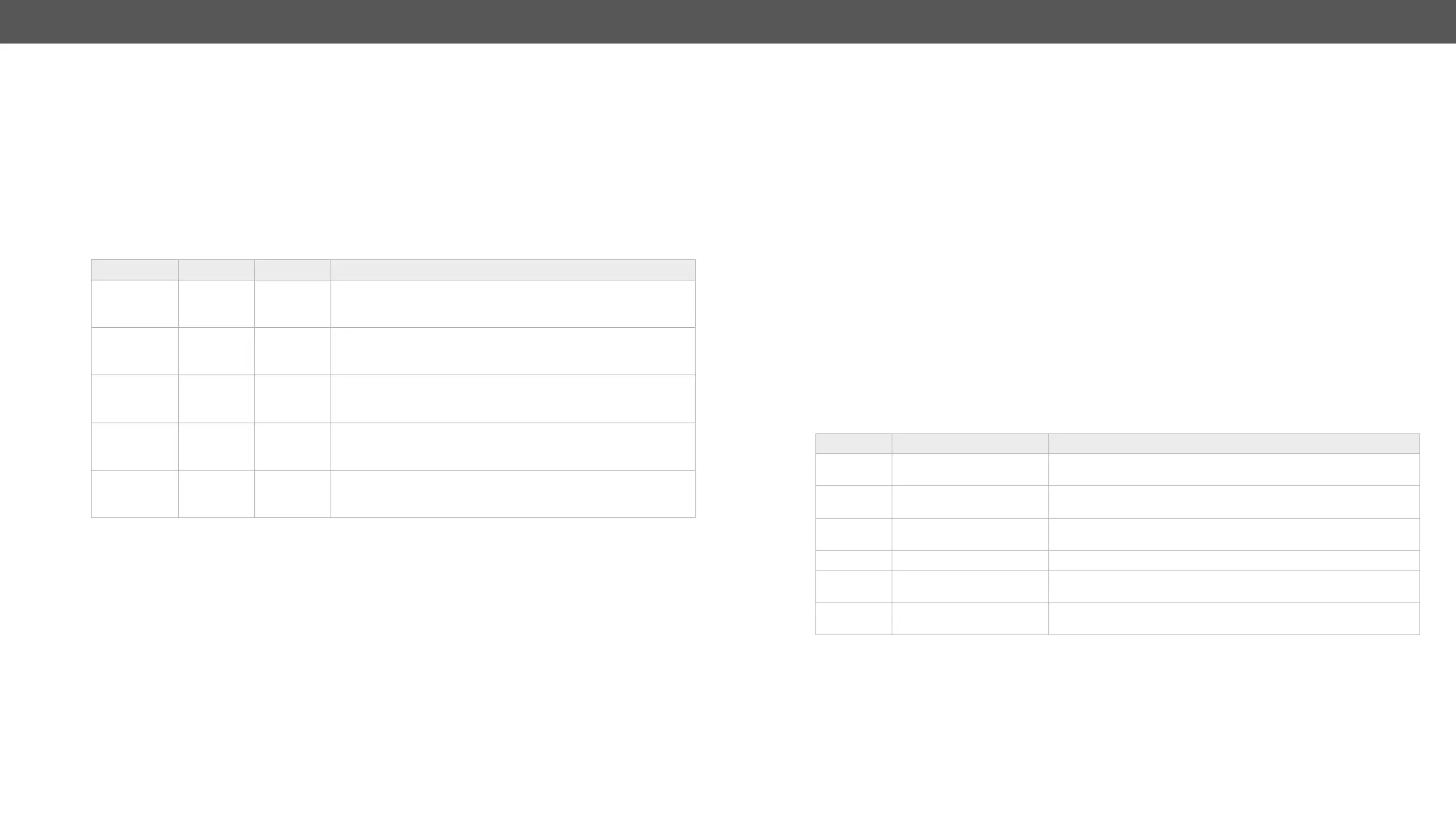
<aud_mode> Analog port Parameter Description
A
(default)
input output
Analog → DVI; Analog → S/PDIF
embedded in the HDMI stream.
B input output
Analog → DVI; DVI → S/PDIF
output and the analog signal is embedded in the HDMI stream.
C output input
DVI → Analog; S/PDIF → DVI
The audio from the HDMI signal is deembedded to the analog
D output input
S/PDIF → DVI; S/PDIF → Analog
routed to the analog output.
E output output
DVI → S/PDIF; DVI → Analog
and analog audio outputs.
Analog Audio I/O Port
Output Port Parameters
Supported Boards
▪ MX-TPS-IB-A, -AP; MX-TPS-OB-A, -AP
▪ MX-4TPS2-4HDMI-IB-A; MX-4TPS2-4HDMI-IB-AP
▪ MX-HDMI-3D-IB-A, MX-HDMI-3D-OB-A
▪ MXD-UMX-IB
Command and Response
ȩ {:AUDOUT#@=?}
Ȩ (AUDOUT#@S=<vol>;<bal>;<bass>;<treb>;<deemp>;<ph>;)CrLf
Example #audio #analogaudio #volume
ȩ {:AUDOUT#9@SI=?}
Ȩ (AUDOUT#9@SI=7800;50;0;0;0;0;)CrLf
The actual setting is in the response; see the legend for the details.
Setting the Parameters
Command and Response
ȩ {:AUDOUT#@=<vol>;<bal>;<bass>;<treb>;<deemp>;<ph>}
Ȩ (AUDOUT#@S=<vol>;<bal>;<bass>;<treb>;<deemp>;<ph>;)CrLf
Example
ȩ {:AUDOUT#9@SI=x;x;6;6;x;x}
Ȩ (AUDOUT#9@SI=7800;50;6;6;0;0;)CrLf
The 'Bass' and 'Treble' parameters changed to '6', the others are left unchanged.
Legend
Parameter Description Parameter Values
<vol> Volume level
Values are accepted between 0 and -78 dB (step is 1 dB) and
rounded. e.g. 8000 = -78 dB; 3625 = -36 dB
<bal> Balance
Values are accepted between 0 and 100 (step is 1):
e.g. 50 = center (default)
<bass> Bass level
Even values are accepted between 0 and 24, other values are
rounded.
<treb> Treble level Accepted values: 0; 2; 4; 6. Other values are rounded.
<deemp> De-emphasis
0 = de-emphasis is disabled
1 = de-emphasis is enabled
<ph>
The phase invert of the
outgoing signal
0 = disabled
1 = enabled
 Loading...