3. Product Overview MX-FR Series Modular Matrix Frames – User's Manual 21
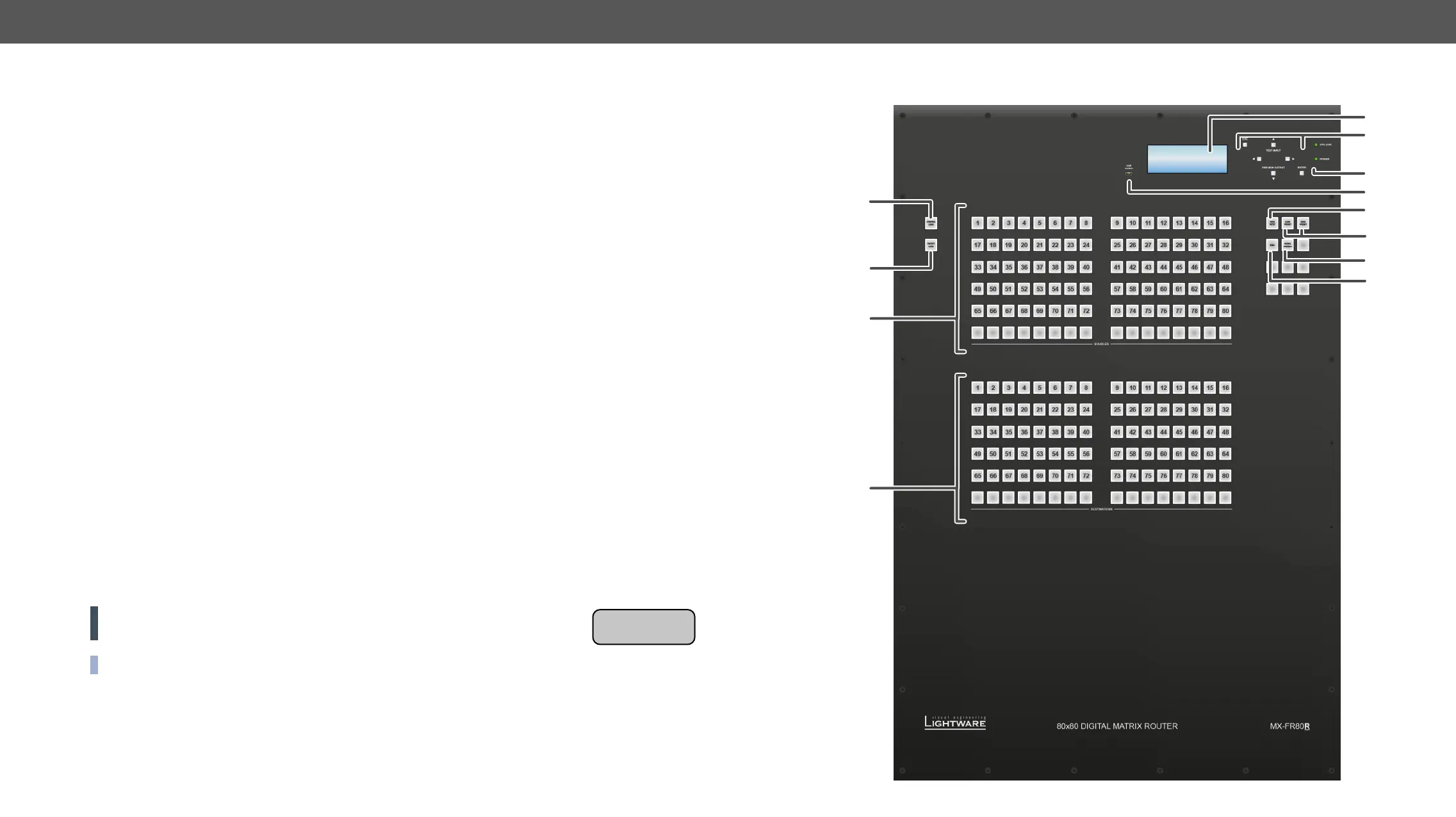
MX-FR80R and MX-FR65R
Front View
1
Menu display Displays status information and menu operation.
2
Menu navigation Up, down, left, right, escape, and enter buttons for menu navigation.
3
Status LEDs CPU live LED blinks to indicate normal operation. Power LED shines green
when the router is powered on.
4
USB control USB connection for Lightware Device Controller Software.
5
Take / Auto Displays the current switching mode of the router (TAKE or AUTOTAKE). Long
press toggles the switching mode, short press executes switching in TAKE
mode.
6
Preset buttons Load preset: apply a previously saved crosspoint preset from one of the
preset memories.
Save preset: stores current crosspoint state in one of the preset memories.
7
Signal present Displays live sources and attached sinks on source and destination buttons.
8
EDID mode Switches the Menu display to EDID menu allowing EDID switch, EDID save etc.
9
Control lock
on the front panel are prohibited.
q
Output lock Locks and protects one (or more) outputs. Inhibits accidental input changing
on the protected output.
w
Source buttons Source buttons have three functions: to select an input, to select a preset and
e
Destination buttons Destination buttons have two functions: to select an output, or to view the
ATTENTION! In the case of the MX-FR65R matrix the attached label can be seen on
the front panel.
INFO: The unlabeled buttons are disabled, and reserved for future developments.
Congured as
MX-FR65R
 Loading...