4. Operation MX-FR Series Modular Matrix Frames – User's Manual 65
Control Protocols
Matrix routers can be controlled with multiple control protocols. Lightware routers have a special protocol,
but to inter-operate with third-party devices, a secondary protocol is also provided.
ATTENTION! Be aware that different control interfaces can be set to use different protocols. E.g. Lightware
protocol is set on Ethernet interface while Protocol #2 is set on the Serial interface at the same time.
INFO: The communication protocol of the USB interface (Lightware protocol) cannot be changed.
The currently used protocol can be viewed or changed any time on the matrix front panel or by protocol
commands.
Step 1. Switch the router to TAKE mode; if AUTOTAKE mode was active, press the TAKE button for 4 seconds.
(light will go off)
Step 2. Press Control Lock button for 3 seconds (it shines red continuously)
Step 3. Press and keep pressing the Output Lock button, the button will shine red. Now the active protocols
for the Serial and the Ethernet ports are displayed (view protocol):
a) One source button lights up according to the current protocol on the Serial port:
– Source#1 lights: Lightware protocol active on Serial
– Source#2 lights: Protocol#2 is active on Serial
b) One destination button lights up according to the current protocol on the Ethernet port
– Destination#1 lights: Lightware protocol active on Ethernet
– Destination#2 lights: Protocol#2 is active on Ethernet
c) The LCD on the front panel shows the active protocols for each interface as well.
Step 4.
a) Release the Output Lock button to keep the current protocol.
b) If you want to change the protocol on any interface, keep the Output Lock button pressed, and press the
desired Source or Destination button
Step 5. If the control protocol for any interface has changed, then a beep will sound to notify the change.
Connect to the matrix through any control interface, then use the commands described in the Changing the
Control Protocol section.
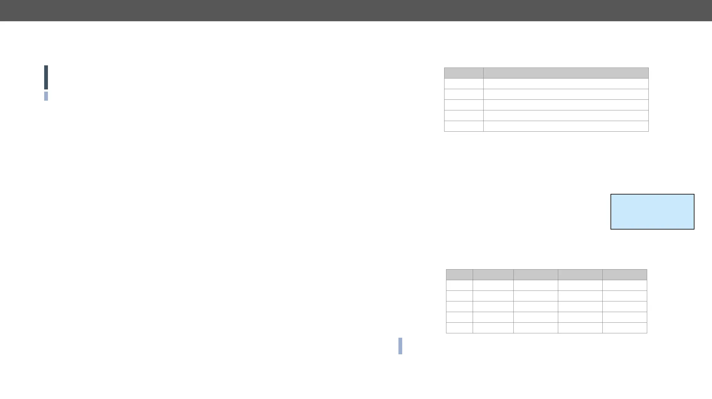
The MX-CPU2 can detect and log many system events. Every log entry gets a time stamp based on the CPU
real time clock. These events are categorized by levels.
Level Description
Notice Not an error. Initialization information.
Warning
Matter Problem that may lead to further errors.
Error Serious error. Must report to support.
Fatal Fatal error. Normal operation is not possible.
and viewed with the controller software.
occurrences and extra information.
that day. The software allows selecting only months and days that have a log.
The matrix can indicate if an error occurred in several ways:
▪ Show alert on the front panel LCD
▪ Send protocol messages when errors occur. The levels for which
this immediate message is sent out can be changed by protocol
command.
▪ Indicate with ALERT LED and SMPTE alarm output on the MX-CPU2 board. If the Alarm LED was
triggered, it remains lit until the frame is rebooted.
Level Name LCD Alert LED, SMPTE RS-232, LAN
0 NOTICE - - -
1 - - -
2 MATTER - yes yes
3 ERROR yes yes yes
4 FATAL yes yes yes
INFO:
that there is any problem with the matrix!
! ATTENTION !
Please check log in
Device Controller
ENTER=View ESC=Exit
 Loading...