EasyManuals Logo
Home>Lightware>Transmitter>UMX-TPS-TX140

Lightware UMX-TPS-TX140 User Manual

Lightware UMX-TPS-TX140
183 pages
To Next Page IconTo Next Page
To Previous Page IconTo Previous Page
Page #47 background imageLoading...
Page #47 background image
4. Device Concept UMX-TPS-TX100 series – User's Manual 47

Advanced IR functionality
DIFFERENCE:      

It is possible in the following ways:
Sending pronto hex codes (
format) section)
Sending pronto hex codes ( format) and Event
Manager section)

Format via IR Port)
Sending Bigger-endian pronto hex code is also available, see Sending Pronto Hex Codes in Big-endian
Format via IR Port.
GPIO Interface
Description
    
    

independently based on needs of the application.
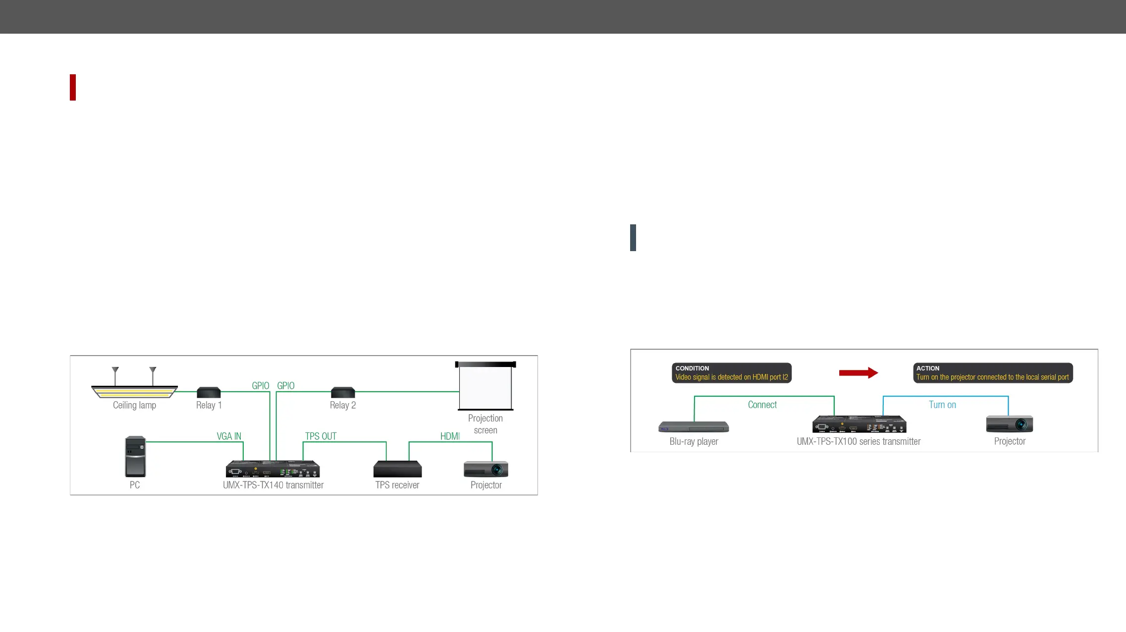
GPIO Options - Example
The Concept
Ceiling lamp is turned off by Relay 1 and projection screen is rolled down by Relay 2 when signal received

Settings of the Transmitter
For Relay 1: create an event in Event manager: when signal is present on Input 1 (I1) then set GPIO pins
to low level for Relay 1 opening. Also create another event when signal is not present on Input 1 (I1)
then set GPIO pins to high level for Relay 1 closing.
For Relay 2: create an event in Event manager when signal is present on Input 1 (I1) then set GPIO pins
to high level for Relay 2 closing. Also create another event when signal is not present on Input 1 (I1)
then set GPIO pins to low level for Relay 2 opening.

send signal to Relay 1 to open which results turning off the lights. Furthermore GPIO pins also send signal


signal to Relay 2 to open so projection screen returns to its enclosure.
ATTENTION! Please always check the electrical parameters of the devices what you want to control. The
maximum current of one GPIO pin is 30 mA, the maximum total current for the seven pins is 180 mA.
GPIO Tab section. See also the details about the Event Manager
settings in the Event Manager section.
The Event Manager Feature
The Event Manager feature means that the device can sense changes on its ports and is able to react


Event Manager example
See more information about the settings in the Event Manager section.

Table of Contents

Other manuals for Lightware UMX-TPS-TX140

Questions and Answers:

Question and Answer IconNeed help?

Do you have a question about the Lightware UMX-TPS-TX140 and is the answer not in the manual?

Lightware UMX-TPS-TX140 Specifications

General IconGeneral
BrandLightware
ModelUMX-TPS-TX140
CategoryTransmitter
LanguageEnglish

Related product manuals