INTRODUCTION 14000 SERVICE MANUAL
1-18
Published 09-05-14, Control # 226-02
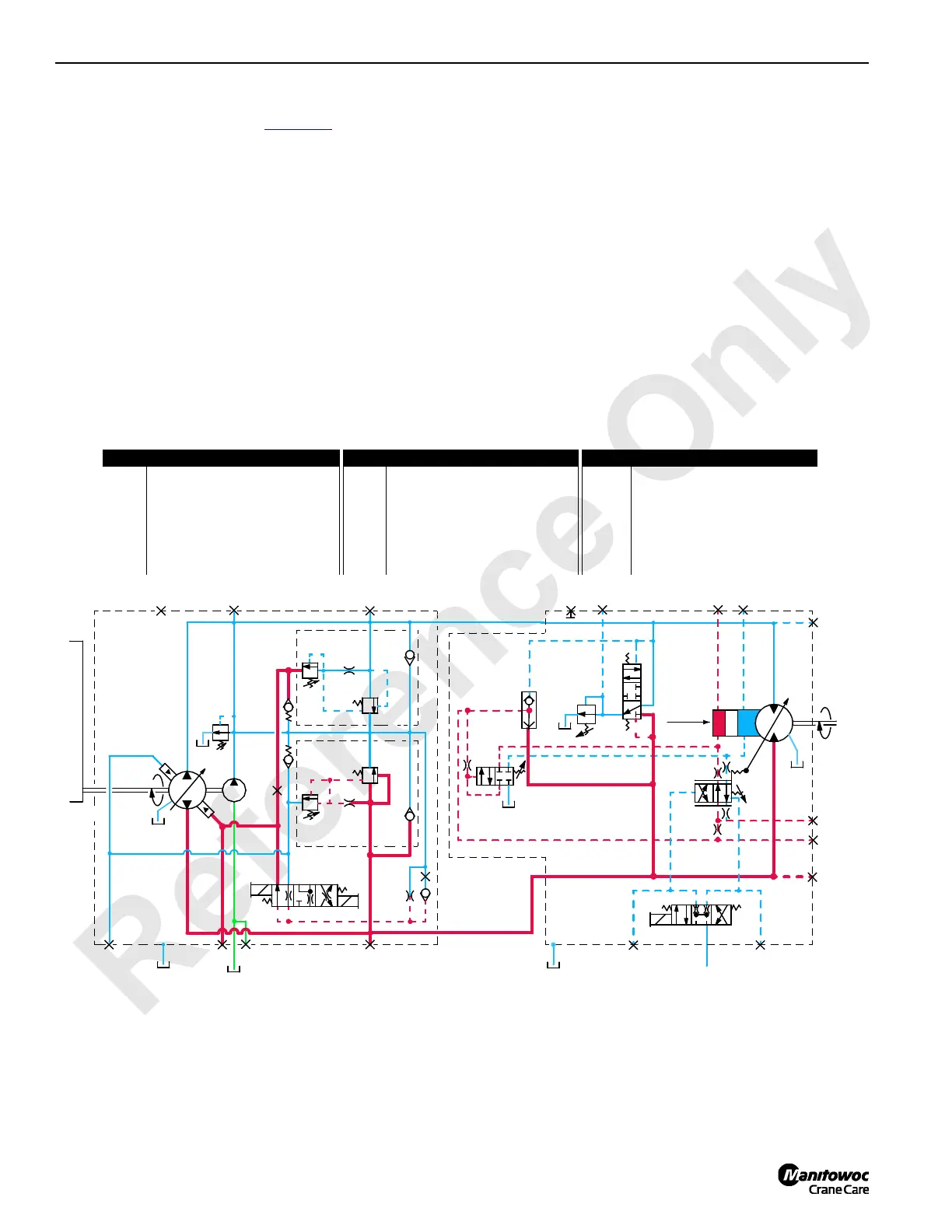
Hydraulic fluid pressure overcomes spring resistance in
pressure limiting relief valve (1, Figure 1-9
), shifting spool to
open a line for fluid pressure. Servo check valve (2) is spring
loaded with an opening pressure of 750 psi (52 bar).
Hydraulic fluid from pressure limiting relief valve flows
through exhaust port of displacement control valve (3).
The exhaust port has a restricted orifice that develops
pressure for servo control cylinder (4) to pressurize and de-
strokes pump to limit system pressure. When rapid loading
produces pressure spikes, system relief valve (5) shifts. This
allows high-pressure fluid to return to tank through charge
pump relief valve (6). Alternatively, fluid transfers to low-
pressure side of closed-loop system through charge flow
make-up check valve (7).
In other system pumps, pressure limiting is controlled
through relief valve section of multifunction valves only. Flow
control orifice (8) is removed from pump EDC. Servo check
valves are removed from pump and lines to servo control
cylinders are plugged. These changes permit the pump to
react quicker to control handle commands.
The pressure limiting relief valve (1) serves as pilot valve to
open system relief valve (5) when desired relief pressure
setting is reached. For example, if a pressure imbalance
occurs on both sides of flow restrictor (9), pressure limiting
valve opens and system relief valve relieves system
pressure. Hydraulic fluid is directed to tank through relief
valve (5) or the flow is transferred to low-pressure side of
system through the make-up check valve (7).
Pump displacement depends on engine driven pump speed
through pump drive and swashplate tilt angle. The engine
provides power for work, while the swashplate tilt angle
provides speed control. Engine speed is set and controlled
with hand or foot engine throttle.
Each variable displacement motor, except travel, begins
operation at maximum displacement (high torque, low
speed) and shifts to minimum displacement (low torque, high
speed) if torque requirement is low. The motor remains in
maximum displacement until servo PC valve (10) receives a
command from PCP valve (11) to direct system pressure and
flow from shuttle valve (12) to minimum displacement side of
servo cylinder (13) that shifts motor. As PCP valve opens in
proportion to output voltage received from the node
controller, pilot line pressure is directed to shift servo PC
valve. After overcoming adjustable valve spring (14) and
valve spring (15), servo PC valve shifts and directs fluid to
T1
T2
T3
3
8
1
2
14
5
16
7
9
11
12
10
15
18
17
13
6
4
FIGURE 1-9
Pump
Motor
Pump Drive
Input
350 psi
(24 bar)
A
D
C
Max.
Disp.
L2
M6
M4 M3
M1
M9
M5
M2
Output
G
M8E
B
M7
A
D
F
A
B
Item Description Item Description Item Description
1 Pressure Limiting Relief Valve 7 Make-Up Check Valve 13 Servo Cylinder
2 Servo Check Valve 8 Flow Control Orifice 14 Adjustable Valve Spring
3 Displacement Control Valve 9 Flow Restrictor 15 Valve Spring
4 Servo Control Cylinder 10 Servo PC Valve 16 ECOR Valve
5 System Relief Valve 11 Pressure Control Pilot Valve 17 Control Valve
6 Charge Pump Relief Valve 12 Shuttle Valve 18 Relief Valve
14CSM1-102

 Loading...


