BOOM RT540E SERVICE MANUAL
4-18 Published 4-20-2015, Control # 502-01
1. Measure and mark the center line of the Fly Section.
This mark will be used to set the adjustable wear pads
after the section is installed in the Outer Mid Section.
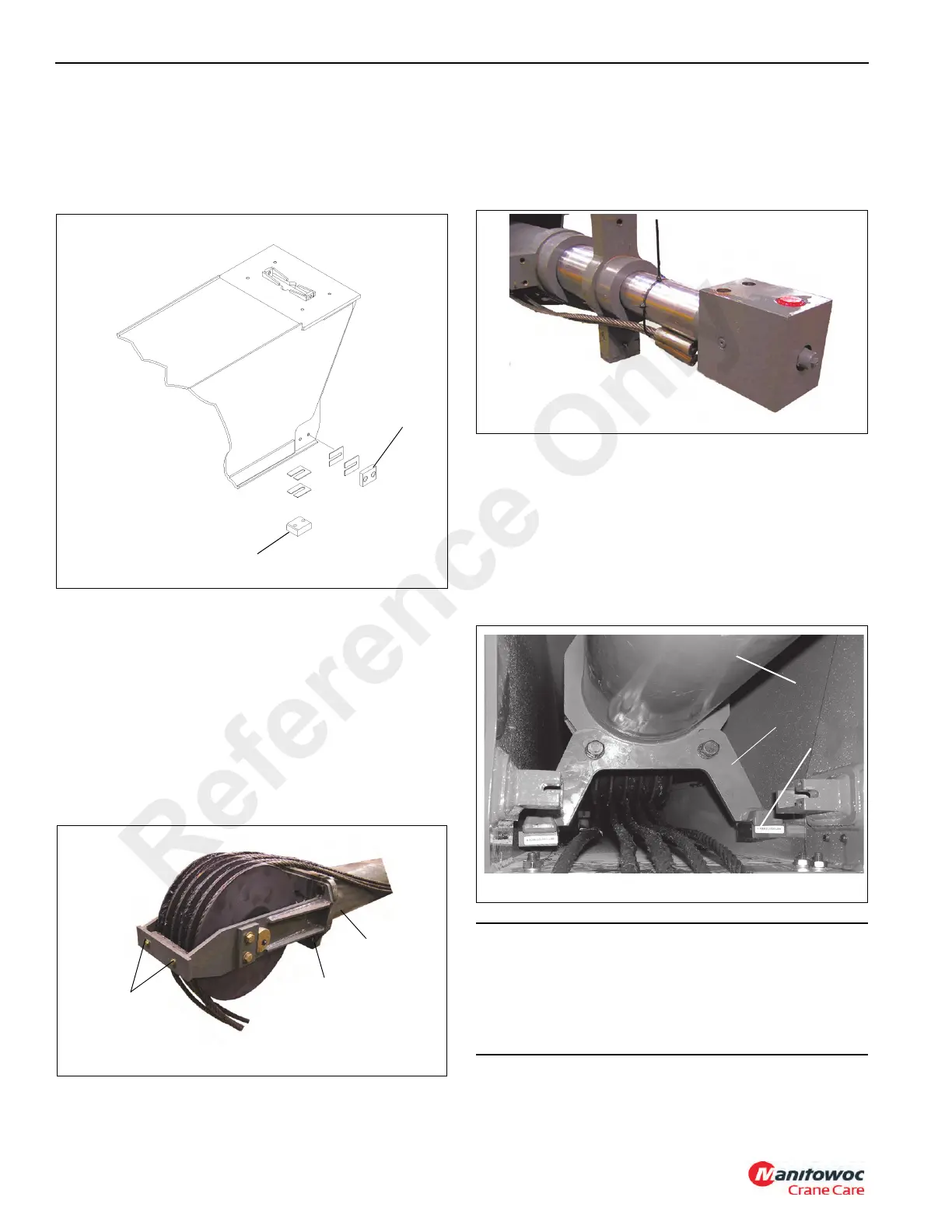
2. Install the lower rear side wear pads (Figure 4-37, 1) and
shims on the fly section with two screws each.
3. Install the bottom rear wear pad (Figure 4-37, 2) on the
fly section with two screws.
4. Install the Tele Cylinder Sheave Mount and sheave
assembly (Figure 4-38, 1) to the Tele Cylinder
(Figure 4-38, 2).
a. Install the sheave shaft with the grease fitting to left.
b. Do not install the cable retainer with hardware
(Figure 4-38, 3) until the Extend Cables are reeved
around the sheave
c. Lubricate the sheave
5. Attach a suitable lifting device to the Tele Cylinder. Raise
the Tele Cylinder.
6. Position the sheave end of the Tele Cylinder at the rear
of the fly section, with port block turned as shown
(Figure 4-39).
7. Carefully insert the Tele Cylinder into the fly section until
the sheave weldment clears the retract cable weldment.
8. Install the two wear pads on the support foot weldment
with two bolts each. Torque bolts.
9. Install the cylinder foot weldment (Figure 4-40, 1) to the
Tele Cylinder (Figure 4-40, 2) using two bolts.
10. Lower cylinder so the cylinder foot weldment rests on
support foot weldment (Figure 4-40, 3) wear pads.
11. Mark BOTH ENDS of the five extend cables
(Figure 4-41).
CAUTION
The five Extend Cables must be marked at both ends
prior to installation. If the cables are not marked, they will
be difficult to install in the correct order.
Do not allow the cables to become entangled or overlap.
Cable or boom failure could result.
Reference Only

 Loading...


