Published 4-20-2015, Control # 502-01 4-19
RT540E SERVICE MANUAL BOOM
.
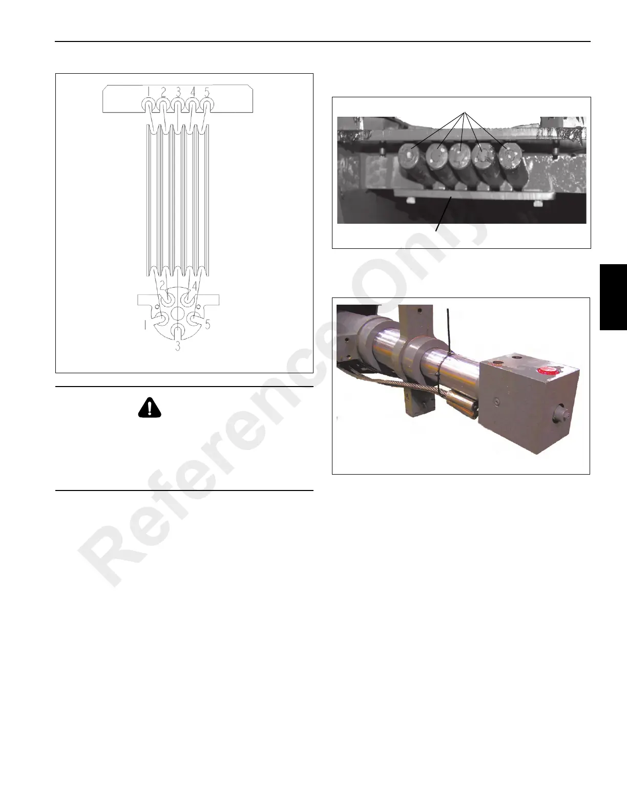
12. Reeve the five extend cables around the Tele Cylinder
sheave.
13. Place the five extend cable dead ends (Figure 4-42, 1) in
the slots at the top of the fly section and secure them
with extend cable keeper plate (Figure 4-42, 2) and two
bolts.
14. Turn cylinder rod mounting lug ends (Figure 4-43) so
they are aligned vertically to clear mounting brackets in
the outer mid section.
15. Slide the Tele Cylinder assembly completely into the Fly
Section.
16. Inspect the extend cables to ensure that they are not
crossed or out of sequence.
17. Place blocking under the rear of the Tele Cylinder to aid
in assembly (Figure 4-44).
CAUTION
When adjusting cables, hold the cable end and turn the
nut. do not turn cable.
Turning or twisting of the cable while adjusting will result
in damage or failure of cable.
Install cables in their natural untwisted condition.
Reference Only

 Loading...


