Published 4-20-2015, Control # 502-01 4-27
RT540E SERVICE MANUAL BOOM
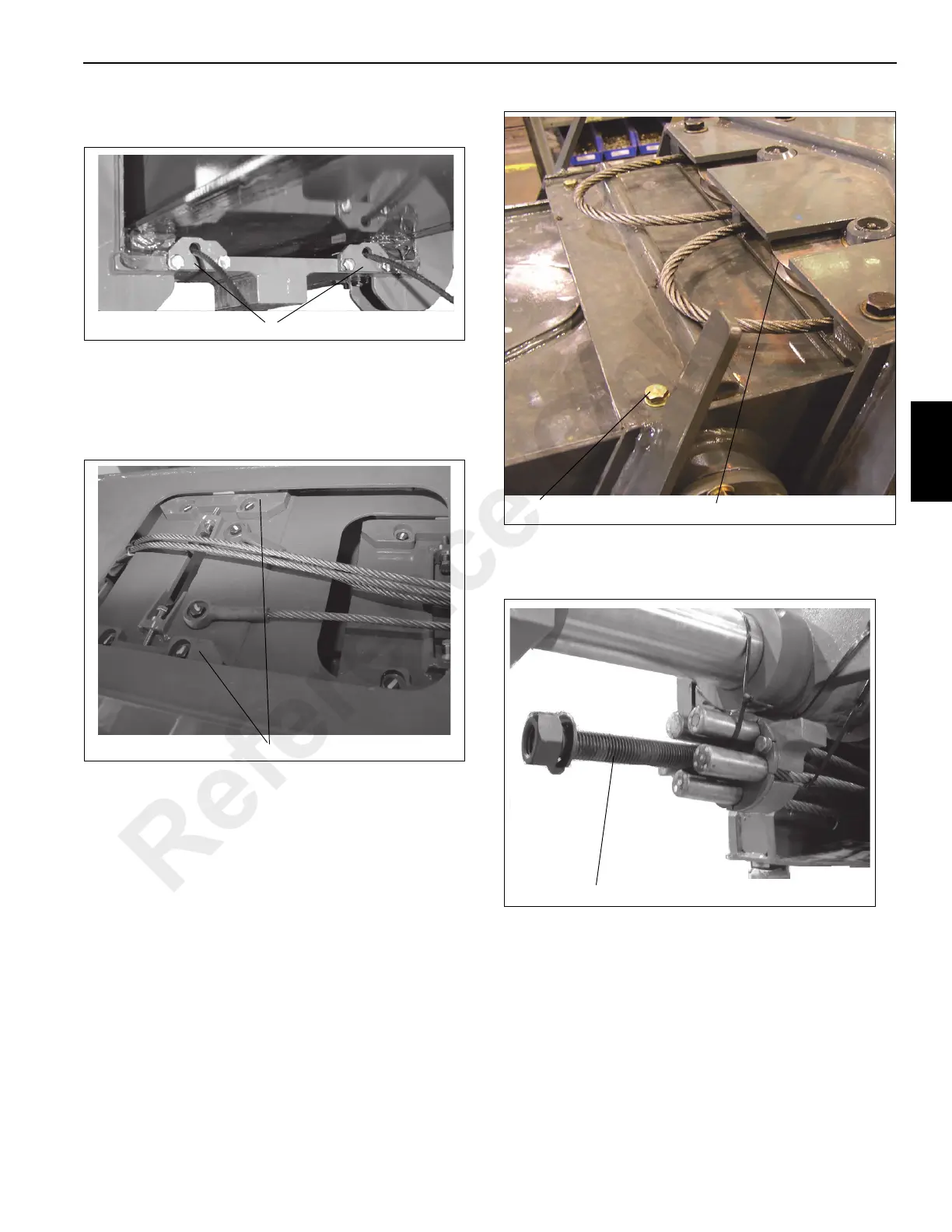
20. Attach fly retract cable anchors to the nose of the inner
mid section (Figure 4-72, 1).
21. Continue inserting the Outer Mid section in the Inner Mid
section. Stop when the upper rear adjustable wear pads
on the Inner Mid section are accessible.
22. Install the adjustable wear pads (Figure 4-73, 1) to the
top of the base end of the Inner Mid section.
23. Install kickback plate on inside top Inner Mid section
(Figure 4-74, 1).
24. Install the mid syncro cable sheave assembly
(Figure 4-74, 2) to top inside of Inner Mid section.
25. Check to make sure the long cable installation bolt
(Figure 4-75, 1) is installed in the extend cable anchor
assembly.
26. Insert the installation bolt into inner mid anchor
weldment and take up as much slack as possible.
NOTE: Make certain that the extend cable anchor is
seating properly into the boom section weldment.
The “ears” on the anchor must fit into grooves
machined into the sides of the inner mid anchor
plate.
Reference Only

 Loading...


