BOOM RT540E SERVICE MANUAL
4-28 Published 4-20-2015, Control # 502-01
27. Carefully clamp the anchor assembly to the Inner Mid
anchor weldment (Figure 4-76).
a. Remove the installation bolt and replace with the
standard adjustment bolt.
b. Take up the slack on the anchor adjustment bolt and
remove the clamps.
28. Adjust the adjustment nut until there is 2.75 inches of
thread showing. Install jam nut.
29. Attach the Tele Cylinder to the inner mid mounting
flanges. Check to ensure bushings are free to rotate
after bolts are tightened (Figure 4-77).
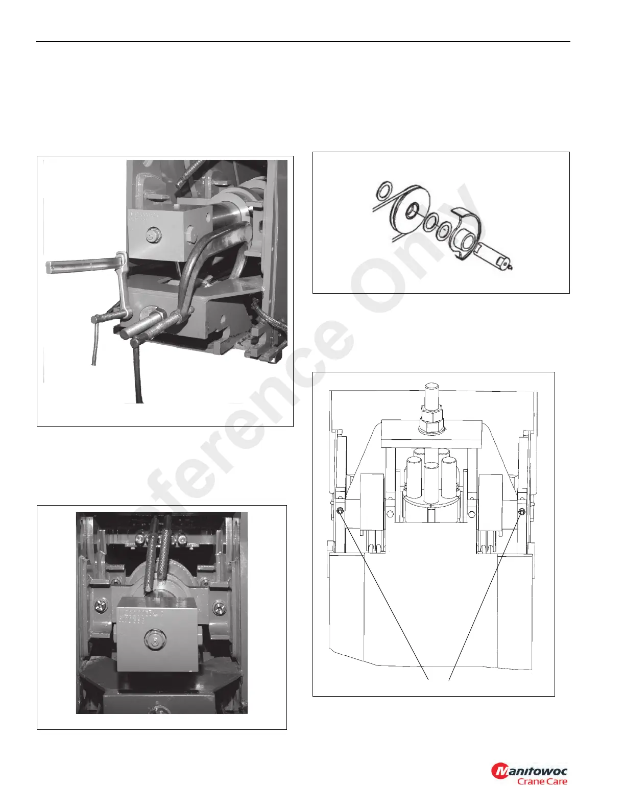
30. Assemble the mid retract sheave assembly as shown in
Figure 4-78 and Figure 4-79. Note that the pin has one
thrust washer to the inside of the boom and two thrust
washers to the outside of the boom.
NOTE: Insert ONE thrust washer to the INSIDE and TWO
thrust washers to the OUTSIDE of each assembly.
31. Reeve the mid retract cables on the left and right mid
retract cable sheave assemblies and install as shown in
Figure 4-78.
32. Install retainer capscrew, washer and nut to lock sheave
assembly pins in place (Figure 4-79, 1).
33. Lay out the mid retract cables toward the nose end of the
Inner Mid section.
FIGURE 4-79
View looking up from the
bottom of Inner Mid Section
1
Reference Only

 Loading...


