MULTI-PORT FUEL INJECTION DISASSEMBLY AND REASSEMBLY
SERVICE MANUAL NUMBER 23
90-861326--1 MARCH 1999 Page 5C-55
CLEANING AND INSPECTION
1. Clean the exterior of the ECM with a dry cloth being careful to avoid contact with connec-
tor pins.
2. Inspect outer surfaces for any obvious damage
3. Visually inspect electrical pins at both ends of ECM for straightness and corrosion.
4. Visually inspect J1 and J2 connectors on the wiring harness for corrosion and terminals
that may have backed out of the harness.
NOTE: The ECM is a sealed electrical component. If a Code 51or 52 check has shown it
to be defective, replace the unit with another ECM having the same part number as the origi-
nal.
INSTALLATION
1. Mount ECM on electrical bracket.
2. Connect J1 and J2 electrical connectors to ECM.
Engine Coolant Temperature (ECT) Sensor
NOTICE
Refer to “Precautions” in this section, BEFORE proceeding.
REMOVAL
NOTE: Handle the ECT carefully as any damage to it will affect operation of the system.
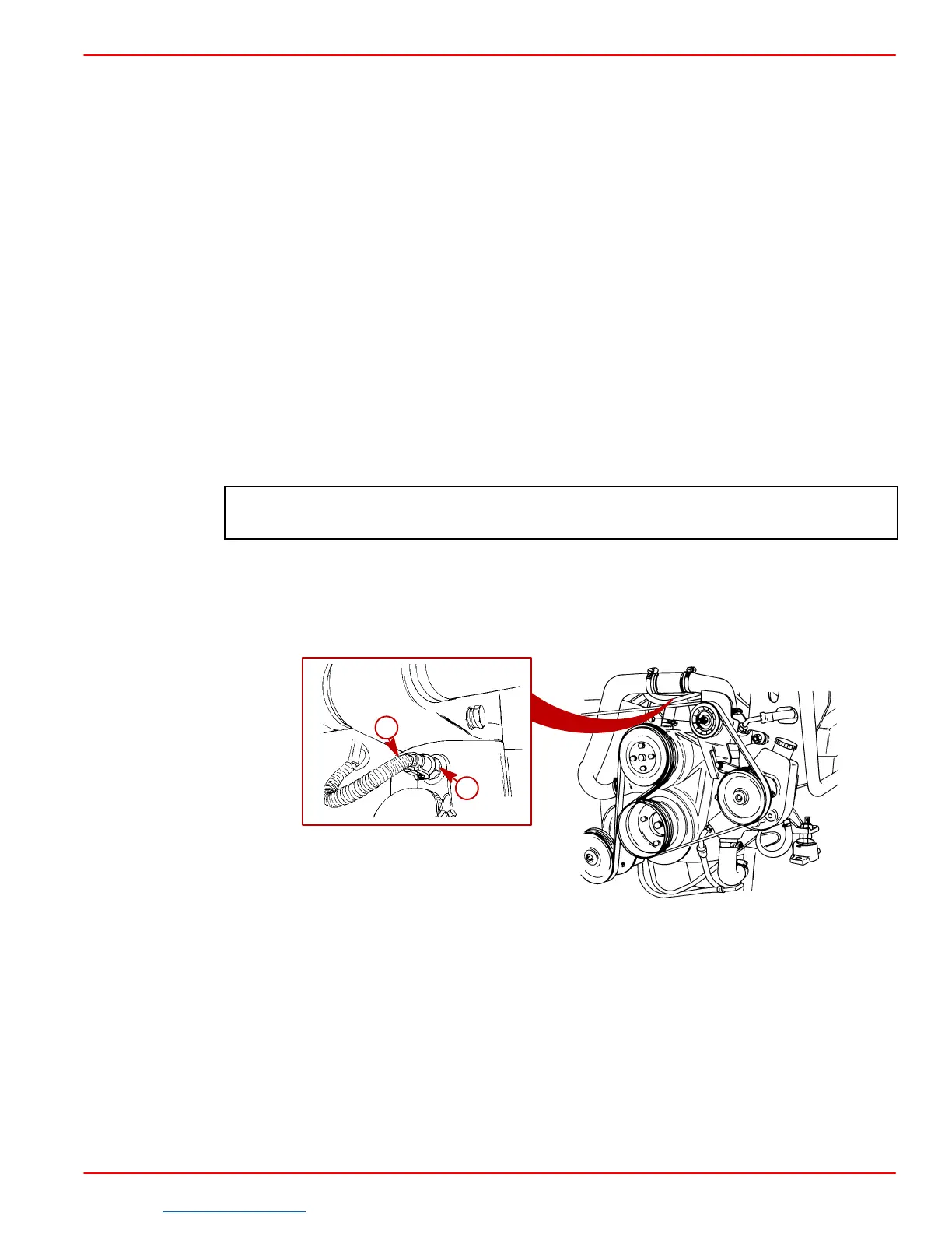
1. Disconnect electrical connector at engine coolant temperature (ECT) sensor.
75484
75671
a
b
a-Engine Coolant Temperature (ECT) Sensor
b-Harness Connector
2. Remove ECT sensor from intake manifold.
CLEANING AND INSPECTION
1. Clean with a dry cloth, removing any excess sealant from the base threads.
2. Look for evidence of physical damage to base or connector surfaces.
Downloaded from https://needmanual.com/!
 Loading...

