Doc# 0296-0018 • REV R (July 2017) Page 13 of 61
CHAPTER 3 - INSTALLATION
A Brief Descripon of Chapter 3
All informaon contained in Chapter 3 pertains to unpacking, cabling, interconnecng, conguraon
and installing the HI 803 TTS and Oponal Equipment. Alternaves to any procedures contained or
implied in this chapter are not recommended. It is very important that the user and service personnel
be familiar with the procedures contained in this chapter, before installing or operang the HI 803 TTS.
METRIX Instruments appreciates your business. Should you experience any problems installing this
equipment, contact your local or METRIX Instruments Inc., Customer Support for assistance.
Unpacking
Step 1. Before signing the packing slip, inspect the packing for damage of any kind.
Step 2. Report any damage to the carrier company immediately.
Step 3. Check to see that everything in the package matches the bill of lading. You should normally have:
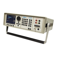
• One Assembled HI 803 TTS Unit
• Power Cord (Prt. #6006-0008)
• Connector, Input to HI 803 (Prt. #2112-0007)
• Special Spanner Wrench (Prt. #0228-0072-01)
• Velocity Transducer Mounng Fixture (Prt. #0228- 0071-02) with screw (Prt. #2824-0135)
• Mounng 1/4-28 Stud Adapters:
1/4-28 Stud - - - - - - - - - - 0228-0070-01
10-32 UNF Stud - - - - - - - - 0228-0070-02
2-56 UNC Threaded Bushing - - 0228-0070-03
6-32 UNC Threaded Bushing - - 0228-0070-04
10-32 UNF Threaded Bushing - 0228-0070-05
• Screwdriver (Prt. #0228-0094-01)
• Operaon and Installaon Manual
NOTE: To ghten the stud adapters to the shaker head mounng hole, use the screwdriver provided
(Prt. #0228-0094-01) in the Accessories Kit. Using this screwdriver insures an adequate load on both
ends of the adapter. Do not apply more than 6 in/lbs of torque to prevent damaging or breaking the
adapter.
Step 4. Write down the Model and Serial number of the instrument. Store this informaon in a conve-
nient locaon for reference when contacng The METRIX Customer Support Department for parts or
service.
 Loading...