Doc# 0296-0018 • REV R (July 2017) Page 26 of 61
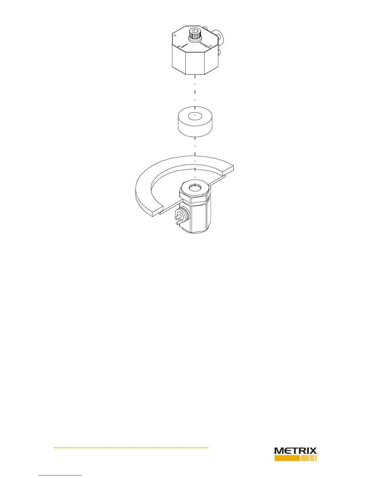
FIG. 3-19 DI-103A INSTALLATION FOR C-AXIS TEST
Step 13. Use the spanner wrench to hold the reference accelerometer. (See Fig. 3-11)
Step 14. Use a torque wrench to ghten the socket head bolt to the ref- erence accelerometer. Tighten
to 18 inch pounds. (See Fig. 3- 19)
NOTE: You can posion the TUT in any of 1 of four direcons.
Step 15. Perform the tests for Axis C. This informaon can be found in the documentaon that comes
with the transducer you are tesng. We use the DI-103A as an example. Make sure to refer to the test
documentaon for the transducer you are cur- rently tesng. This informaon may dier from manufac-
turer to manufacturer. If you have more than one transducer to test, complete the test for the C Axis for
all the transducers. This will save a lot of me.
Step 16. When all the tests are complete, use the allen wrench and loosen the socket head bolt unl you
can remove the accelerometer.
Installing Printer Paper
Step 1. Change the paper roll when a red strip appears on the paper.
Step 2. Remove the printer from the HI-803 chassis. (See Fig. 3-20)
• Loosen the two capve screws and carefully li the printer out of the chassis.
• Do not detach the cable.
 Loading...