Doc# 0296-0018 • REV R (July 2017) Page 18 of 61
Chadwick-Helmuth Velocimeter
#7310 Test Setup
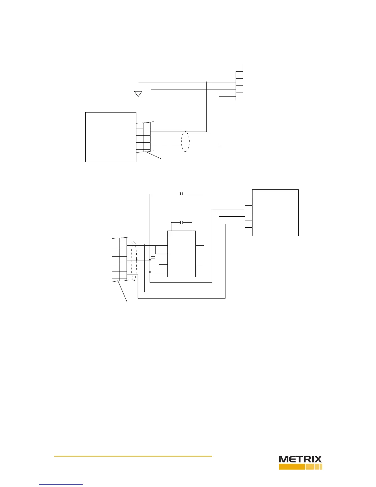
The following informaon provides the electrical diagram for connect- ing the Chadwick-Helmuth Velo-
cimeter #7310 to the TTS. (See Figs. 3-9 & 3-10)
A
D
C
B
VELOCIMETER
MODEL
#7310
TTS
4
2
GND
CHANNEL A
+V
GND
-V
GND
SIG
TTS INPUT PLUG
PRT. #2112-0007
-V = -5V TO -15V
+V = +5V TO +15V
@ 0.4 AMPS
EXTERNAL POWER
(FLOATING)
FIG. 3-9 EXTERNALLY POWERED (FLOATING) ELECTRICAL SETUP
A
D
C
B
VELOCIMETER
MODEL
#7310
TTS
4
2
GND
CHANNEL A
GND
SIG
TTS INPUT PLUG
PRT. #2112-0007
3
+9V
6 4
1
5
7
8
+IN -OUT
LT1026
NC
GND
NC
+
+ 1 uF
.1 uF
23
-8.3V
+8.9V
FIG. 3-10 TTS POWERED ELECTRICAL SETUP USING A SPECIAL CIR- CUIT (CONVERTS + TO -) LOCATED IN
HOOKUP CABLE PRT. #0215- 0102-01
Triaxial Accelerometer Installaon
Installaon of the Mounng
Bracket and Cables
Step 1. ALWAYS use the Spanner Wrench (Prt. #0228-0072-01) to prevent damage to the Reference Ac-
celerometer when installing the mounng bracket or a test accelerometer. (See Fig. 3- 11)
 Loading...