Doc# 0296-0018 • REV R (July 2017) Page 9 of 61
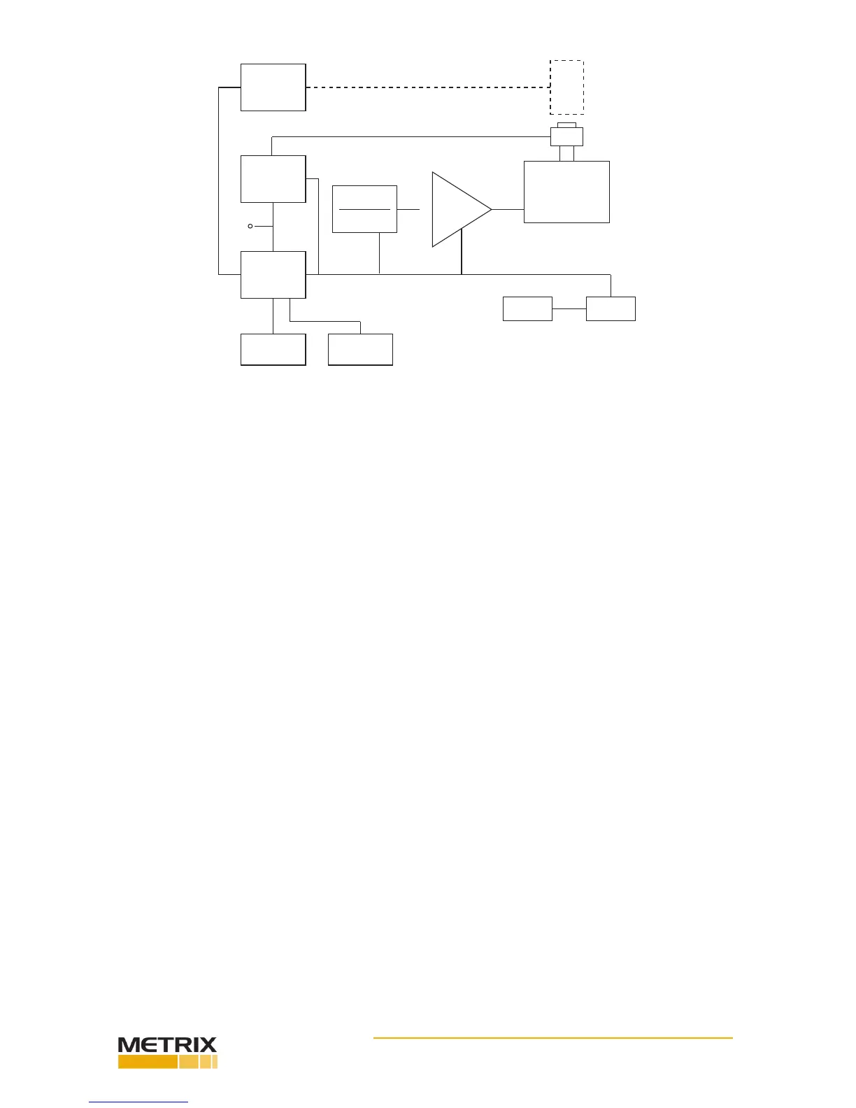
FIG. 1-1 TRANSDUCER TEST SET (TTS) - BLOCK DIAGRAM
Baery Operaon
The TTS can be operated using an AC line power source or from its internal
rechargeable baeries. No switching is necessary since AC line power is always connect to
a built-in baery charger thereby providing a charge whenever connected to power. Maxi-
mum charge rate is achieved when the TTS is o.
Baery power for the TTS is supplied by two (2) sealed solid gel rechargeable baeries. The
baeries are designed for connuous charging without damage. Baeries should be kept
fully charged. Under nor- mal operaon, the TTS will operate in excess of 4 hours with fully
charged baeries.
Charge life is directly dependent on the power used which is established by the test require-
ments. When tesng requires high force be supplied to drive the test transducer (due to
heavy xturing or transducer size and/or due to high test levels) the charge life will be
shortened.
CAUTION A COMPLETE DISCHARGE CAN CAUSE BATTERY FAILURE.
A protecon circuit switches the TTS o automacally. When this occurs, the TTS must be
connected to AC power to acvate its charger right away. Under normal condions baeries
will obtain a full charge aer (8) hours charge me. If deep discharge occurs, one or more
days may be required to reach full charge.
Special Handling and Storage
The internal baeries are sealed and should provide long term service under normal operat-
ing condions. They are securely mounted heavy duty brackets so that no damage can occur
from shipping or normal transportaon. No special handling should be required.
TUT
AMPLIFIER
ASSEMBLY
Ref Accel
Amplifier
Assembly
Micro
Computer
and
Keyboard
DISPLAY
Sine
Generator
Freq
Ampl Adjust
Power
Amplifier
Assy
Electrodynamic
Shaker
PRINTER
CHARGER BATTERIES
TUT
Ref
Out
 Loading...