Doc# 0296-0018 • REV R (July 2017) Page 24 of 61
Step 2. While sll holding the spanner wrench in place, use the allen wrench provided with the bracket
kit to screw the mounng bracket socket head screw into the reference accelerometer. (See Fig. 3-9)
Tighten the screw so that the bracket is snug against the reference accelerometer. If you want, use a
torque wrench and torque to 18 inch pounds. Do not over torque the mounng screw. Overghtening
the mounng screw can cause bad readings.
Step 3. Install the connecng cable (Prt. # 0214-0088-01) between the Transducer under test (TUT) and
the input connector on the top panel. (See Fig. 3-12)
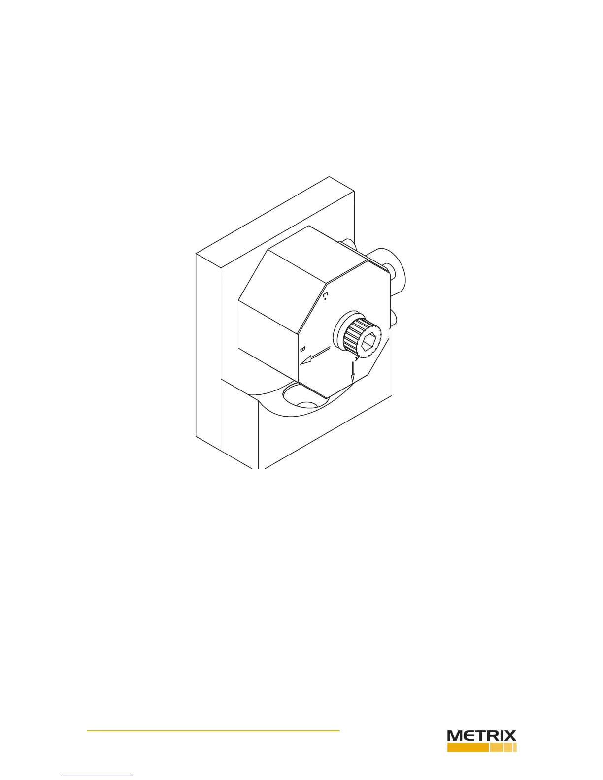
Step 4. Posion the TUT for the A posion. (See Fig. 3-17)
Step 5. Screw the socket head bolt into the mounng bracket. Use a torque wrench and ghten the bolt
that fastens the transducer to the bracket to 18 inch pounds. Do not overghten.
Step 6. Perform the tests for Axis A. This informaon can be found in the documentaon that comes
with the transducer you are tesng. We use the DI-103 as an example. Make sure to refer to the test
documentaon for the transducer you are currently using. This informaon may dier from manufac-
turer to manufacturer. If you have more than one transducer to test, complete the test for the A Axis for
all the transducers before moving on to Axis B or Axis C. This will save a lot of me.
Step 7. When all the tests are complete, use the allen wrench and loosen the socket head bolt unl you
can rotate the transducer to the Axis B posion. (See Fig. 3-18)
FIG. 3-17 DI-103A A-AXIS POSITION WITH A ARROW POINTING DOWN
 Loading...