Doc# 0296-0018 • REV R (July 2017) Page 25 of 61
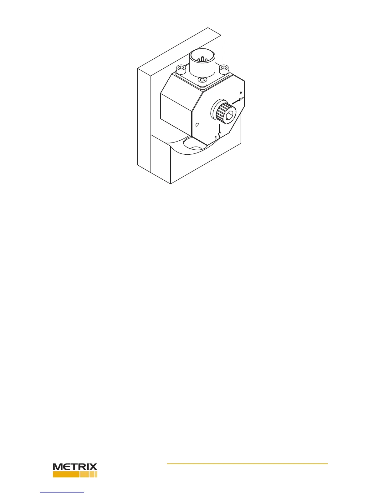
FIG. 3-18 DI-103A B-AXIS POSITION WITH B ARROW POINTING DOWN
Step 8. Screw the socket head bolt into the mounng bracket. Use a torque wrench and ghten the bolt
that fastens the transducer to the bracket to 18 inch pounds. Do not overghten.
Step 9. Perform the tests for Axis B. This informaon can be found in the documentaon that comes
with the transducer you are tesng. We use the DI-103 as an example. Make sure to refer to the test
documentaon for the transducer you are currently tesng. This informaon may dier from manufac-
turer to manufacturer. If you have more than one transducer to test, complete the test for the B Axis for
all the transducers before moving on to Axis C. This will save a lot of me.
Step 10. When all the tests are complete, use the allen wrench and loosen the socket head bolt unl you
can remove the accelerometer from the bracket.
Step 11. Use the allen wrench provided and remove the mounng bracket socket head screw. Take
the mounng bracket o the reference accelerometer and store it in secure locaon. Do not store the
bracket in the kit bag provided, because it might damage the reference accelerometer when closing the
lid.
DI-103A Installaon for the C-Axis Tests
Step 12. Slide the spacer (Prt. #0205-0049-01) over the socket head bolt that fastens the Transducer
Under Test (TUT) to the refer- ence accelerometer. (See Fig. 3-19)
 Loading...