Doc# 0296-0018 • REV R (July 2017) Page 15 of 61
Installaon Procedures
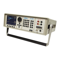
TTS to TUT Cable Connector
Pin Out Diagram (See Fig. 3- 1)
FIG. 3-1 CABLE CONNECTOR PIN OUT DIAGRAM
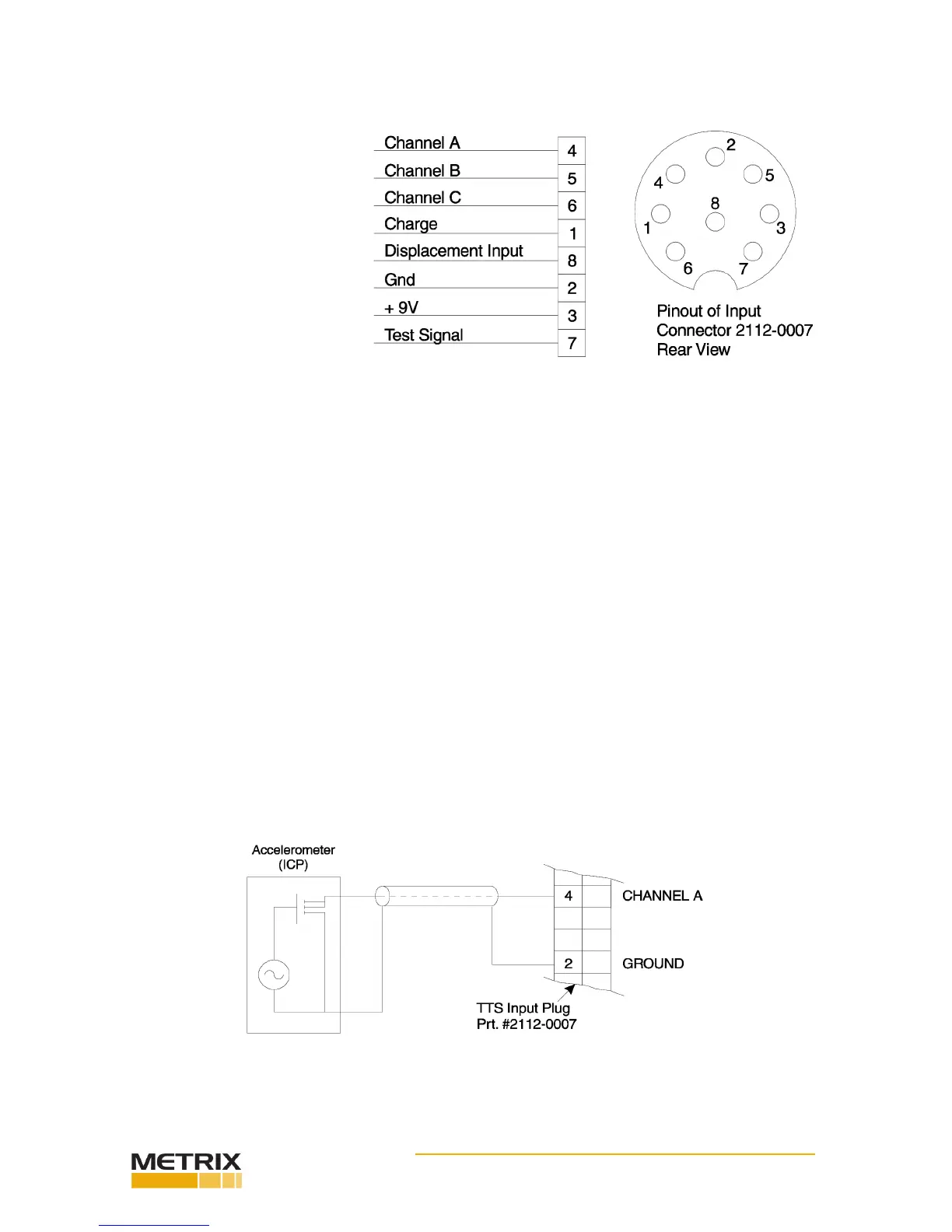
Channel A Input for all transducers that provide voltage outputs. Current can be selected by
menu for those transducers requiring current between.5 mA and 6 mA for power.
(See Fig. 3-2)
Channel B & C Use ONLY when tesng triax accelerometer (ICP type) (See Fig. 3-4)
Charge Used for charge accelerometers with a sensivity between 10 PC/g to 100 PC/g
(See Fig. 3-3)
Displacement Input For proximity type displacement transducer with voltage output between 0 and
-24 volts.
GND TTS signal ground
+5V Regulated +9V output at 6 mA maximum
Test Signal Test signal output for use with loop back test cable.
Accelerometer - ICP Type
FIG. 3-2 ACCELEROMETER ICP TYPE
 Loading...