Assembly Installation Guide
2 - 6 0070-10-0683 AS3000™ Service Manual
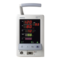
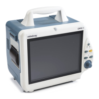
2.2.11 Monitoring Products - Mounting and Electrical Connection
1. Any monitoring system compatible with the GCX mounting system's swivel head may be
mounted to the AS3000’s arm.
NOTE: Use of other monitors and mounting hardware is the
responsibility of the installer.
2. Always make full use of all mounting fasteners and strap capturing devices when
mounting monitors to the AS3000.
3. After mounting a monitor to the AS3000, connect it to one of the AC outlets located on
the rear of the AS3000.
a. Turn on each monitor one at a time and ensure that the circuit breaker holds without
tripping.
b. Dress each line cord neatly along the side of the anesthesia machine so that it can
not be easily pulled or extend far from the main chassis.
2.2.12 Agent Monitor Waste Gas Scavenging
1. Respiratory gas monitoring products have an exhaust port from which waste gas expels.
The exhaust port on the gas monitor must be connected to the open barbed fitting on the
waste gas scavenger.
2. Ensure that a tight connecting fitting is attached to the rear of the gas monitor. Ensure
that the other end of the same tube has a tight fitting connection attached to the waste
gas scavenger’s (WGS) barbed fitting.
3. Dress the exhaust tubing neatly along the side of the anesthesia machine so that it can
not be easily pulled or extend far from the main chassis.
2.2.13 Oxygen Sensor Calibration
NOTE: See ‘‘Periodic Maintenance Schedule of Service Activities’’
on page 6-2 for when to calibrate the oxygen sensor.
1. Preparing the unit
a. Allow the breathing system to warm up and reach thermal equilibrium
(approximately 30-60 minutes).
b. In Standby mode, press the MENU button. The menu screen will appear.
c. Select Service, then input the password 2010 to enter the Service screen.
d. Select Calibration to enter the Calibration screen.
e. Select Oxygen Sensor to enter the Oxygen Sensor Calibration screen.
2. Calibration
NOTE: Do not shake the O
2
sensor during calibration.
NOTE: During calibration, keep the O
2
sensor in a vertical position,
connector side up, and bottom side exposed to room air;
keep the O
2
sensor near the heated block to minimize the
temperature difference from within the heated block.

 Loading...