Part II General Information
Product Principle 122
2 Product Principle
2.1 General Structure of Hardware System
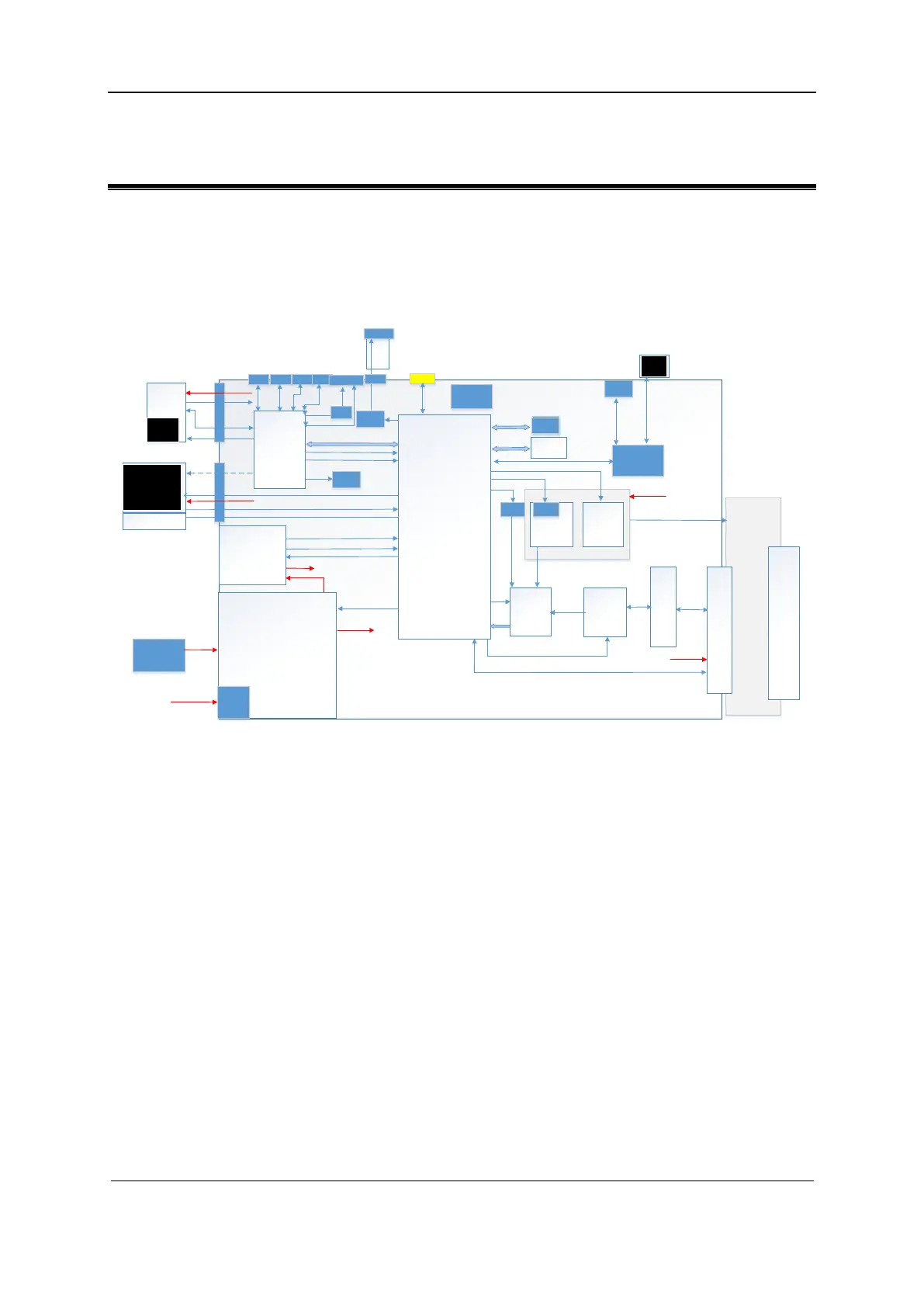
Figure 2-1 Schematic diagram of the hardware system
PC module
AFE
Transmission
chip
HVSW
DC-DC
Battery
AC_IN
AC_IN
LCD
15.6
To uch
Panel
Pr obe
conne
ctor
ATGC
4D&TE E
ADC
CW
Clock
ne tw ork
POWER
4D_Con tr ol
Data BUS
SPI
con tr o l
RX 64
ATGC
CW I /Q
ATGC SPI
CW SP I
Transmission control SPI
4D驱动信号
P O UT
64
P O UT
128
Probe POWER
Probe mana geme nt
PCI E x1
Main board
LAN
WIFI
SSD
HDMI
USB3.0 *4
LCD_C on tr o l
DC-D C POWER
Power synch ron izati on
LCD_C on tr o l
LCD P OWER
eDP*2
AUX
DP*2
AUX
Et he rn et
USB3.0*4
USB2.0*4
USB2.0*2
DDR BUS
Monitoring of
Switch
Management
Syst em
UART
DDR
DDR
FAN
POWER
POWER_BTN
BATA POWER
Ambient light
sensor board
I2C
MF_DSP_TR FPGA
JE DS x 16
ADBUFFER
DDR BUS
Probe board
260pin
Pr obe
socket
IO b oa rd
S-video
HUB
Convers
ion chip
HDMI
RGB
PHV
PHV POWER
DC-D C POWER
PHV Synchronization
UART
Sca n stat us i ndicati on
CODEC
4D&TEE&CW board
USB2.0
OLED
SPI
HDA
HDD
eDP*2
AUX
USB2.0
The preceding figure shows the composition of the MX hardware system, which mainly
comprises the following units:
Main board:
˗ DC-DC module: DC-DC circuit for supplying power and charging/discharging the
battery
˗ PHV module: PHV circuit for providing PHV and HV power for the transmit circuit
˗ Backend functional circuit: implementing audio, video, IO interface, and other
functions
˗ FPGA module: implementing video processing, IO interface control, transmit/receive
control, and signal processing
˗ Transmit/receive channel: 64 channels
˗ HV switch module: implementing adaption between 64 channels and 128 channels
˗ Probe related control interface
˗ Power management (EC): power management and control for starting or shutting down
the main unit
˗ System monitoring (SM): power and fan monitoring for the main system
 Loading...


