Part II General Information
Product Principle 131
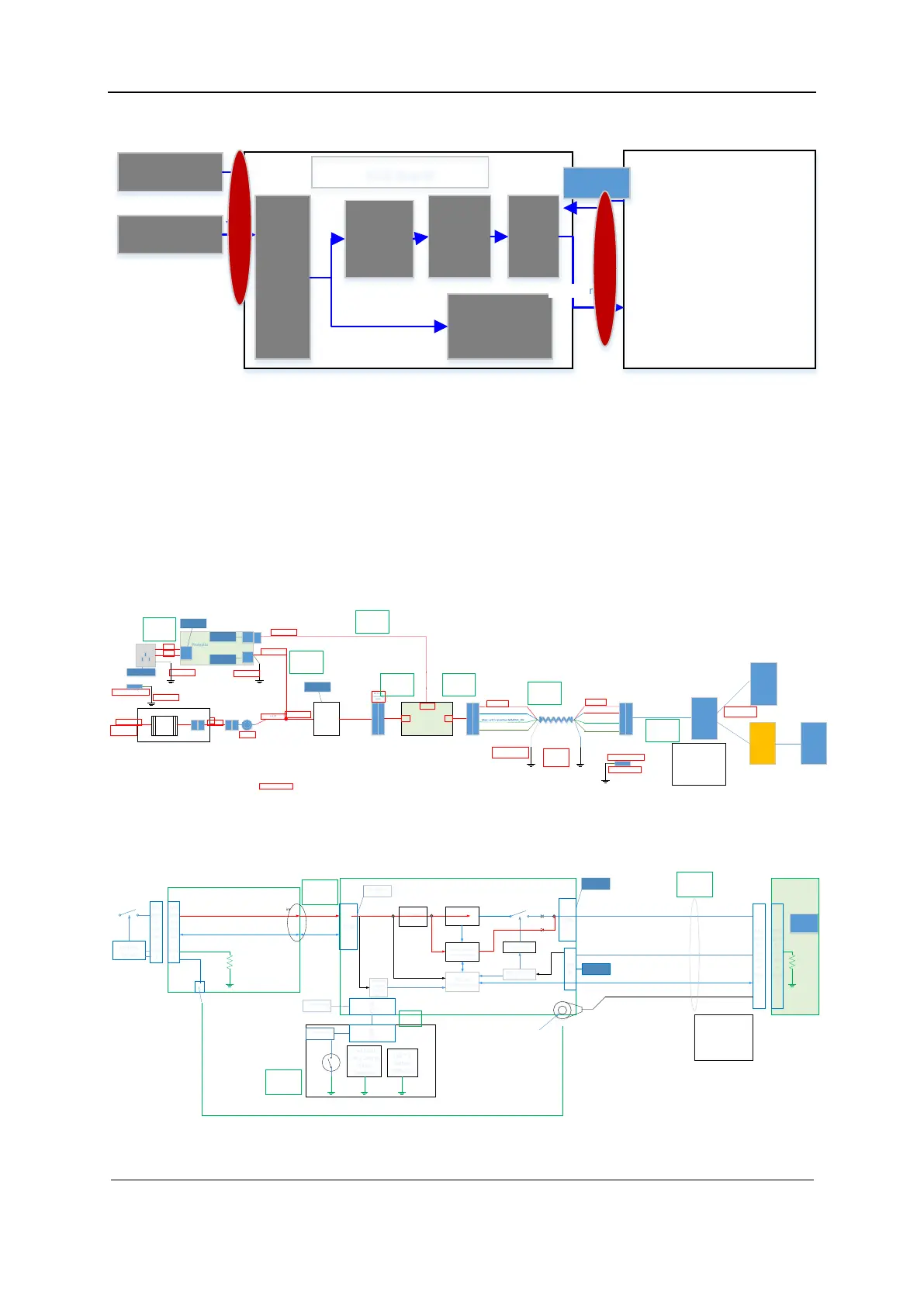
Figure 2-10 Block diagram of the ECG module
Main Board
ECG le ad
DC IN
Socke
t Port
Magnif y
Filterin
g
Samp
li ng
Heart rate
test
Serial port
ECG Boa rd
Pwr
C
T
B
C
T
B
2.10 Trolley Power Supply
The trolley power supply is used to power the main unit system. When AC input is available, the
main unit system is powered by AC_DC power. When there is no AC input, the main unit system
is powered by the trolley battery. The trolley power supply comprises the protection and indicator
board, AC-DC power, output control board, and battery package (trolley battery management
board, battery magnetic connection board, key and indicator board, and 2–4 chargeable lithium
ion batteries). The following figures show the connections among the components.
Figure 2-11 Connections among boards of the trolley power supply
网电源
Win der
Mai ns pow er
MX:
AC-DC 150 W
19V
Protection and AC indication
board
Auxiliary
output
WTB
Equ ipoten tia l pole
0509-20-00098
WT
B
WT
W
WT
W
L,N,PE
L,N,PE
L
N
Fixed to sh eet met al
Fixed to sheet
met al
WTB
WTB
Vout
Main unit serial po rt UART
Magnetic
interface
Vout
Main unit serial po rt
UAR T
Grou nd
WT
W
Air-to-air
connecting
piece
Ground
WT
W
Main unit in p osition
MAST ER_ON
PIN1 l arge ---DC-
PIN2 l arge ---DC+
PIN3 l arge ---DC+
PIN4 sm all---CA RT2MB
PIN5 sm all---MB2CART
PIN6 l arge ---con nection status
mas ter-on
PIN7 l arge ---PE
PIN8 l arge ---DC-
MX main unit
Batt ery
package
MX main unit
Alternativ e
connection
LED
indicati on
power
1
2
3
Res erved EMC an d grip
inter ference prev ention
mea sure
2+
2-
FG
NC
2+
2-
FG
TX
RX
Master_ON
L,N,PE
L,N,PE
Output control
board
WT
W
WT
W
2+
2-
FG
NC
WT
W
WT
W
2+
2-
FG
TX
RX
Master_ON
Shiel d layer connecti ng to the
ground terminal
Equipotential pole 0509-20-
00098
Fixed to the sheet metal
of the bench
Bond wire
Bond
wire
Bond
wire
Shield layer to t he
she et met al
through the
ter minal
9
1011
12
L,N,PE
WT
W
WT
W
Mag neti
c ri ng
PGN D
PGN D
Fixed to sh eet mtal
TE7 trolley adapter:
022-00 0194-00
M39-0002 23---
1*2
2100-10 -07944
M32-0420 02-00
1*4 3.96
M32-0320 02-00
1*3 3.96
Figure 2-12 Connections among boards of the trolley battery package
CON
DC inpu t
Ma
gne
tic
suc
tio
n
hea
d
commun
ication
DPM
Bat tery char ge
and dischar ge
MCU a nd
peri phera l circ uits
Auxiliary
power
suppl y
circuit
Hot-swap
circuit
Magnetic
absorber
Battery management
board
Control
circuit
Output
control
Contro l circuit
Output
control
Hot-swap
circuit
Ma
gne
tic
suc
tio
n
hea
d
Ma
gne
tic
suc
tio
n
hea
d
Ma
gne
tic
suc
tio
n
hea
d
MX
Vo ltag e
detection
Magnetic suc tio n
dete ction c ircui t
Welded wire
CON
Led * 5
battery
indication
Led Dual
Color Charge
Status
Indicator
CON
Indicator
board
CO
N
CON
PIN1大---DC-
PIN2大---DC+
PIN3大---DC+
PIN4小---CART2MB
PIN5小---MB2CART
PIN6大---连接状态masteron
PIN7大---PE
PIN8大---DC-
2+
2-
Master_ON
DC+,DC-
TX,RX
Mas ter O N
PE
TX
RX
1
2
3
4
Welded wire
Welde d stud
008-000690-00
2*5
008-000220-00
2*6
008-000220-00
2*6
008-000736-00
2*2
M32-060006-00
1*6
 Loading...


