Part II General Information
Product Principle 126
Circuit Unit Function
Ultrasound related
functional circuit
Transmit/Receive control
Probe control
4D and TEE probe control (reserved function)
PHV control
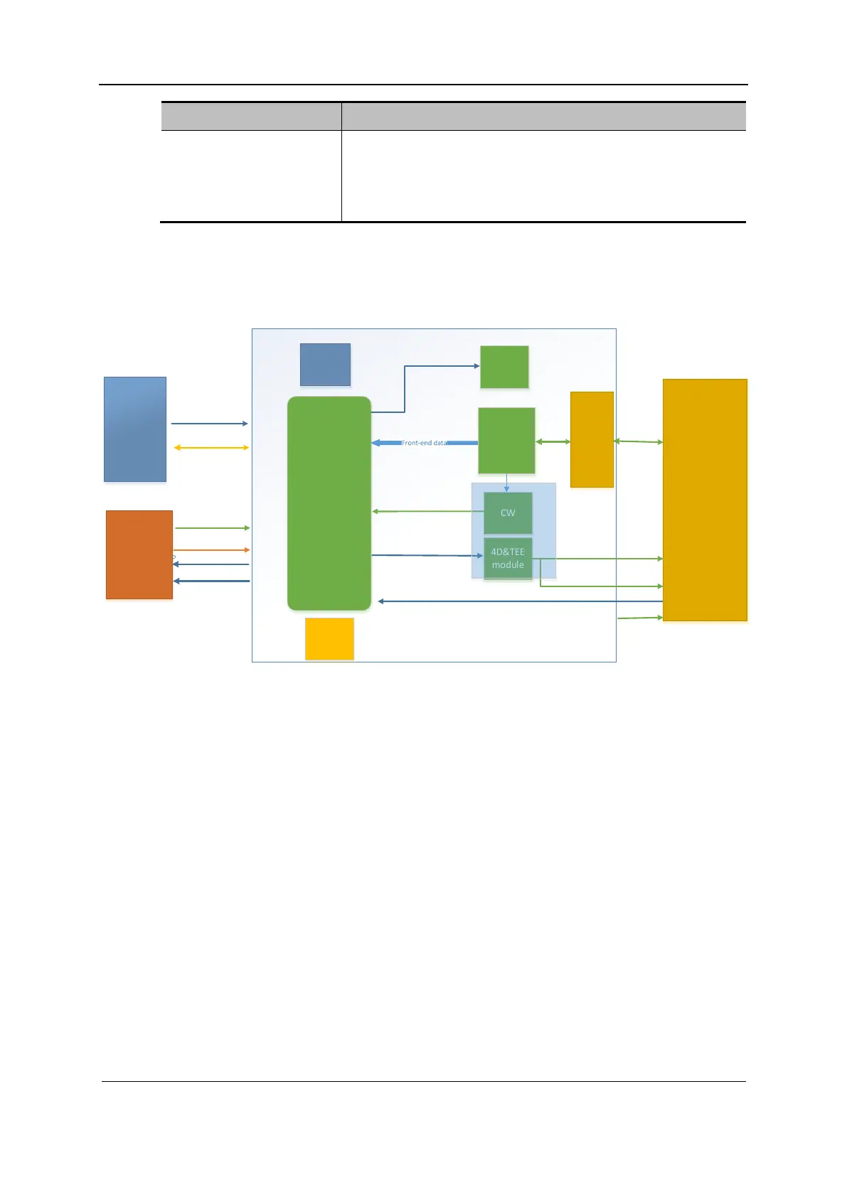
2.2.3 Frontend of the Main Board
Figure 2-5 Block diagram of the frontend system of the main board
DSP_TR_FPGA
Front-end
modul e
TR module
4D&TEE
modul e
ATGC
modul e
DDR
CW
PCIE bus
Front-end power
PHV control
PHV input
Power synchronization
reset
POUT64
Probe management
4D&TEE
Clock
modul e
CW dat a
IQ dat a
ATGC control
4D control
Probe in position/ID
HV
switch
POUT128
Back-end
module
Power
module
UI module
Probe power supply
4D&CW&TEE board
The main board frontend provides the following functions:
Control FPGA, implementing transmit/receive control, ATGC adjustment, CW receive
control, and probe management for 64 channels
Clock circuit
Transmit circuit, transmitting pulses to send 5-level signals
HV switch circuit, implementing expansion from 64 channels into 128 channels
AFE, receiving echo signals
ATGC circuit (time gain compensation)
2.3 Probe Board
Supporting nominal probes including 192/128-element probe, phased array probe, and dual-
plane probe
Connecting between the main unit and the probe
Switching to 192-element mode inside the probe (only 129 channels are supported on the
probe board)
 Loading...


