Part II General Information
Product Principle 123
Probe board: connecting the probe to the main unit
COME module (or PC module): Doppler running platform
Multifunctional board (optional): implementing the 4D&TEE&CW functions
Main display module: 15.6'' display capable of sensing the brightness of ambient light.
Image screen: showing the equipment model and the battery level of the main unit and
trolley.
Touch screen: 12.3-inch touch screen for adjusting system parameters.
Control panel: enabling key operations for the entire main unit. It is the signal input of the
main unit.
DC connection board: connecting the magnetic adapter to the main unit.
S-Video connection board: implementing the S-Video interface function.
2.2 Main Board
The main board consists of three parts: power supply, frontend, and backend.
2.2.1 Power Supply
The power supply comprises two parts: PHV and DCDC.
2.2.1.1 DCDC Power Supply
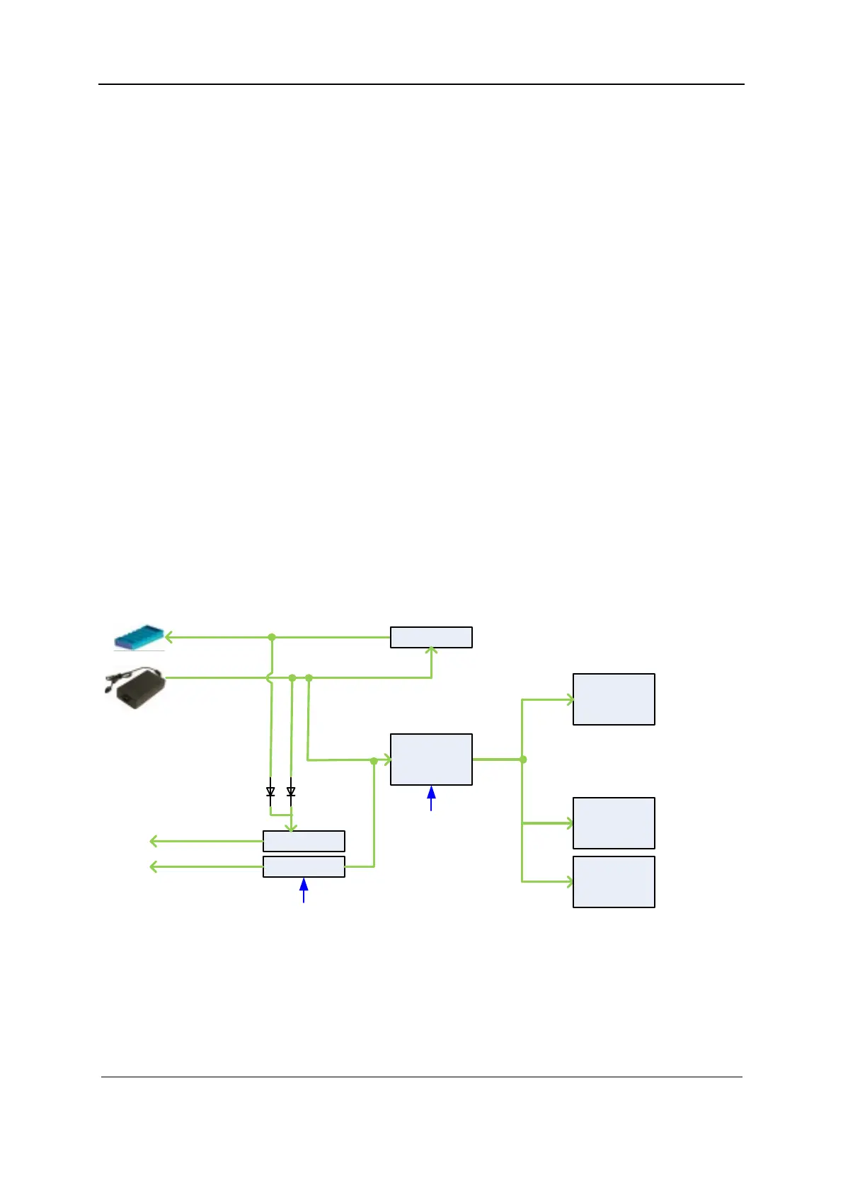
Figure 2-2 Block diagram of the DCDC power supply
12VBUS
(12A)
Buck
Charger
2.5A Ch g
4.6A Dsg
19.0V/7.9A
AC/BA T
DCDC
DCDC
3V3STB(1A)
5VSTB(3A)
(240mA)
PWR_12V_EN_N
5V STB _EN
DCDC
DCDC
DCDC
……
1V
1.2V
1.5V
5V
2V
3.3V
……
Function description:
The DCDC power supply provides power when the main unit stands by or is powered up.
The DCDC power supply provides battery charge and discharge circuits.
 Loading...


