Part II General Information
Product Principle 129
The PSOC debugging interface and FPGA/JTAG interface on the control panel should be
convenient for debugging.
The control panel contains the AC status indicator, battery status indicator, and disk status
indicator. Indicator details are confirmed based on UI requirements.
2.7 Main Display Unit
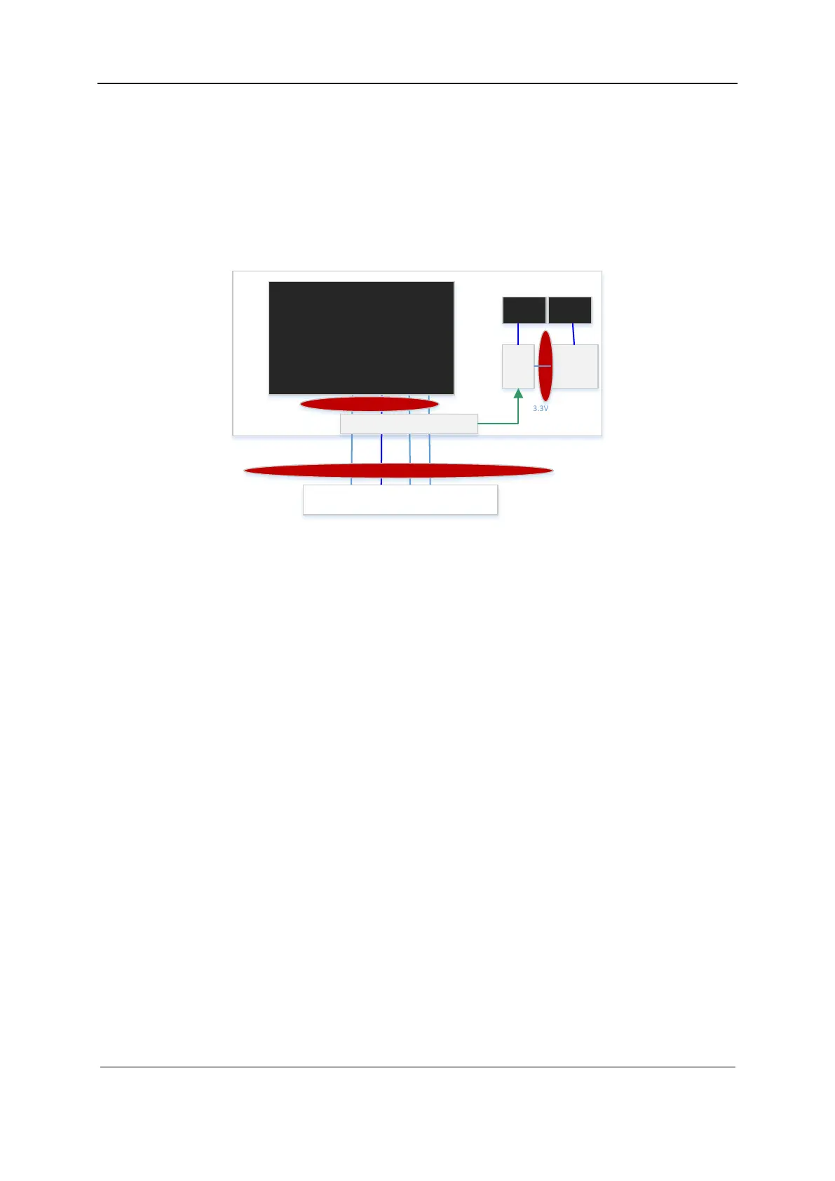
Figure 2-8 Block diagram of the display
OL ED
Transfer
board
OL E D
board
+12V+3.3V
eDP
3.3V
I2C
Backlight
co ntr ol
3.3V_STB
serial port
主板插座
15.6"
1920*1080
LCD Moni t or
CTB c onnec to r
CTB c onnec to r
CTB c onnec to r
2.3"A MO
LED
2.3"A MO
LED
OL ED t ransfer board
The display unit consists of the LED display, two 2.3'' AMOLED display cables, secondary
screen conversion board, secondary screen board, and OLED conversion board.
Function description:
The secondary screen conversion board stores color temperature and gamma correction data,
and works with the LCD screen to ensure display consistency. Related parameters in the
control board should be updated at initial installation or upon control board/LCD screen
replacement.
The main board FPGA will correct video signals output by the industrial control board based
on information in the secondary screen conversion board, and then drive the LED display.
The display brightness and power are also controlled by the main board FPGA.
The secondary screen board is used to light up the two 2.3'' AMOLED displays. It also
integrates the MCU to implement display and power control, and the ambient light sensor to
detect the brightness of the ambient light. Moreover, it integrates the distance sensor to
support waking up the display through touching or short-distance gesture.
The OLED conversion board converts AMOLED display and power signals from the
secondary screen board. It also integrates the distance sensor.
 Loading...


