Part II General Information
Structure and Assembly/Disassembly 176
5.1.2 Trolley
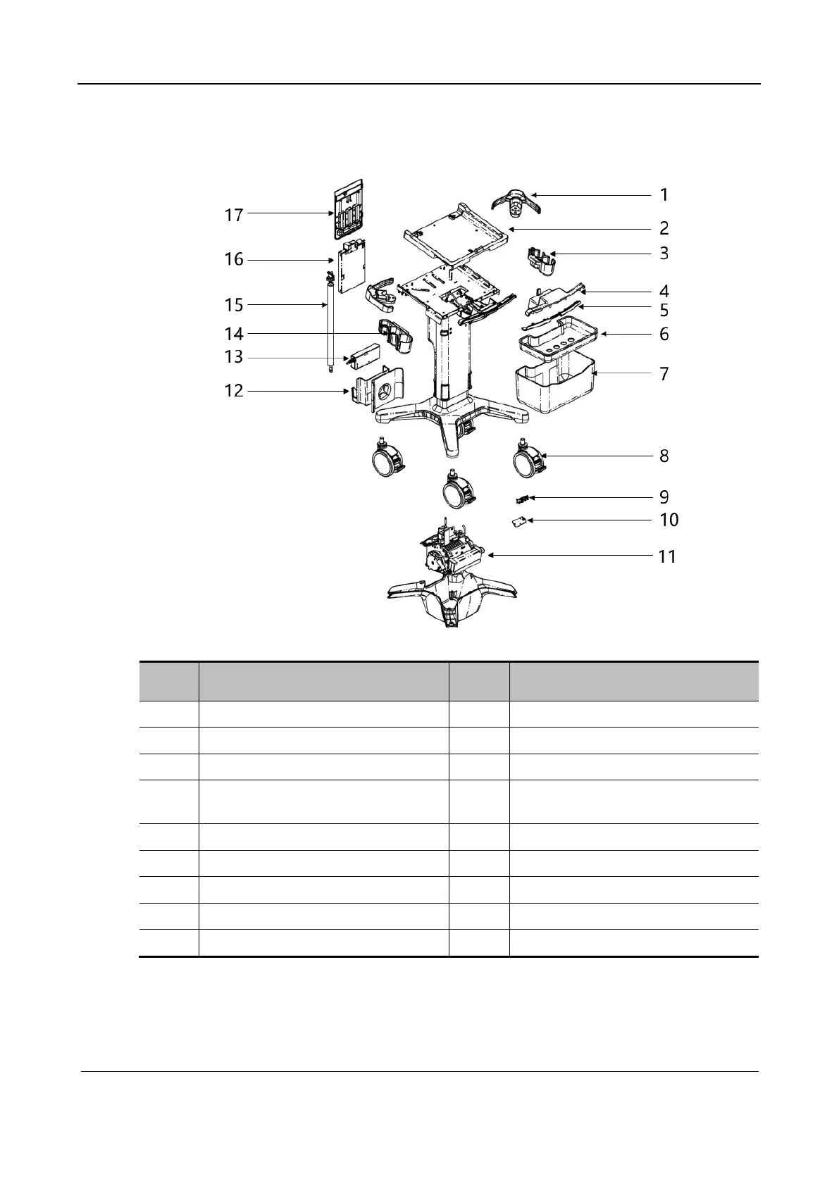
Figure 5-2Explosive view of the trolley
No. Name No. Name
1 Protective Bracket 10 Mobile Trolley Output Control Board(
2 Trolley Control panel Top Cover 11 Retractor
3 Right Probe Holder Assembly 12 Adapter Basket
4 Mobile Trolley Handle Upper Cover 13 Power adapter (applicable to the main
unit, absent for the trolley)
5 Mobile Trolley Handle Front Cover 14 Left Probe Holder Assembly
6 Small Tray 15 Gas spring
7 Big Basket 16 Probe extender
8 Caster 17 Probe extender cover plate
9 2146 Fuse and LED Board PCBA
5.2 Assembly/Disassembly of the Main Unit
This section describes the assembly and disassembly processes of major components and hardware
boards. The assembly process is the inversed disassembly process unless otherwise specified.
 Loading...


