Part II General Information
Function and Performance Check 229
6.5 Performance Test
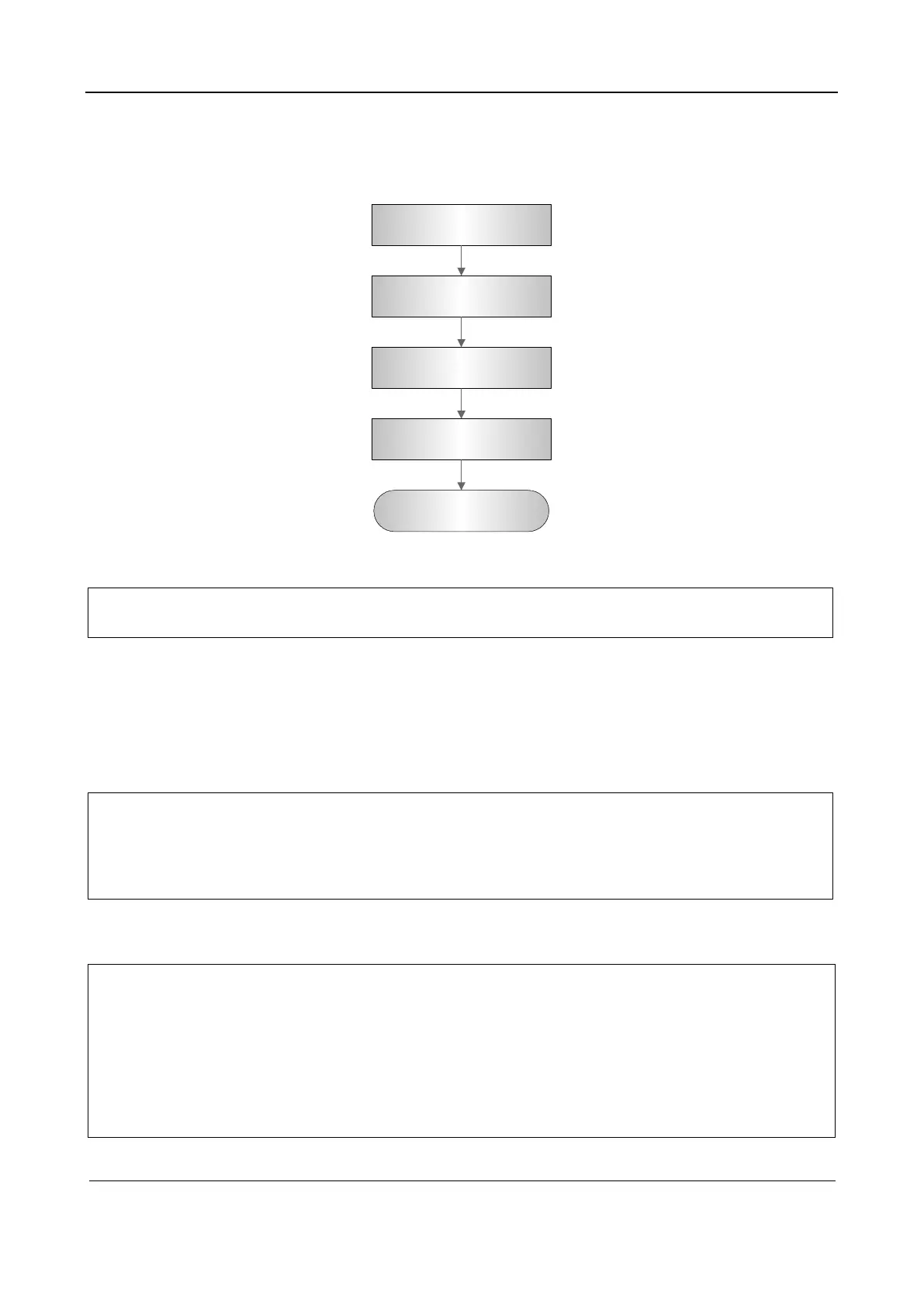
6.5.1 Test Procedure
Check resolution
Check detection depth
Check geometric
positioning accuracy
Blind area test
Record the imaging
6.5.2 Test content
Note:
The following figure is only used for reference in the testing, and the actual image effect
depends on the specific system.
Requirements:
Display: set the brightness and contrast values to clinical (or default) status;
Ambient: dark room to simulate actual clinical using;
The probe surface should contract with the acoustic window without separation or pressing.
Note:
For details about the phantoms required for the test, see Part III Appendix: 4Phantom
Usage Illustration.
Phantom KS107BD, low frequency, used when center frequency of the probe ≤4MHz;
Phantom KS107BG, high frequency, used when center frequency of the probe ≥5MHz;
6.5.2.1 Transverse resolution
Note:
For convex probe, keep the transverse resolution targets near the central line of the
scanning plane.
For linear array probe with Steer function, DO NOT turn on Steer when testing the
transverse resolution.
Magnify (zoom) the targets for observation if necessary.
Distance between the left and right edges of a target point at a certain depth indicates
the transverse resolution at this depth also.
 Loading...


