Part II General Information
Product Principle 128
No. Board Function Description
1 Control panel Trackball, custom function keys, backlight control, system
status indicator, encoder, and buzzer
2 Switch button board Power-on/off and cover opening detection, with partial
power-on/off status indication functions
3 Touch screen 12.3-inch LED display, working with the main display for
operation control and supporting the touch function
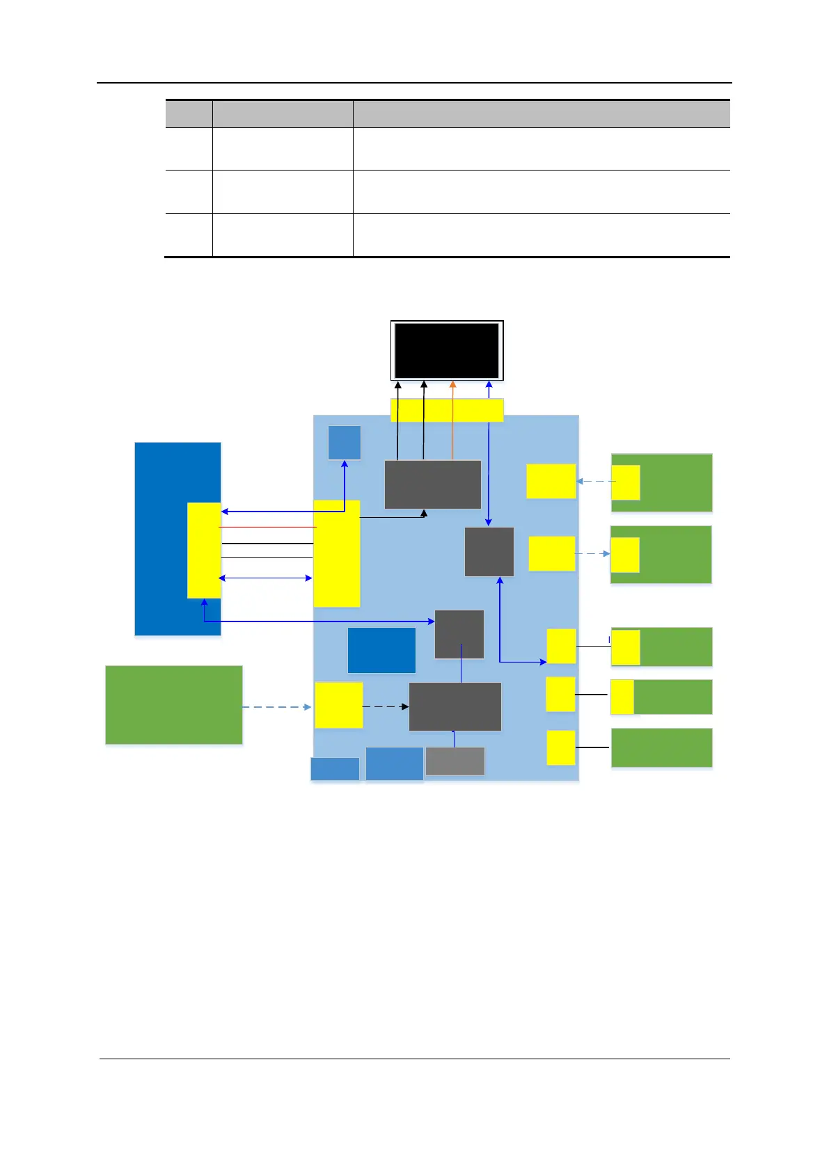
Fig 2-7 Block diagram of the control panel
Control
panel
PSOC
Main
board
BTB
socket
FPGA
CFG
Flash
TGC
board
Touch
panel
USB2
BTB
socket
PC
keyboard
DP/eDP
+12V、+5V
Indicators
sig nal
SPI
JT AG
socket
PSOC
Calibration
socket
WTB
Speaker
FPC
connector
FPC
conn
ector
FPC
connector
WTB
WTB
sig nal
sig nal
Matrix signal
Extended
keyboard
FPC
conn
ector
FPC
connector
Button
sig nal
LED drive
circuit
USB2.0
HUB
EDP TO LVDS
FPC connector
Touch
screen
LVDS
USB2.0
sequence
control
LCD POWER
USB2.0
HALL
LCD_SW_N
WTB
WTB
Trackball
USB3
The preceding figure shows the block diagram of the control panel. The function modules are
described as follows:
The PSOC+FPGA solution is adopted for main control of the control panel.
The control panel implements key functions and LED drive, and confirms indicator
conditions based on UI requirements.
The control panel supports the touch screen.
The PSOC of the control panel communicates with the main unit through a USB port. The
main unit provides a USB port.
The FPGA of the control panel employs the AS configuration mode.
The M7 trackball or touch panel are supported and mutually exclusive.
 Loading...


