Part II General Information
Product Principle 125
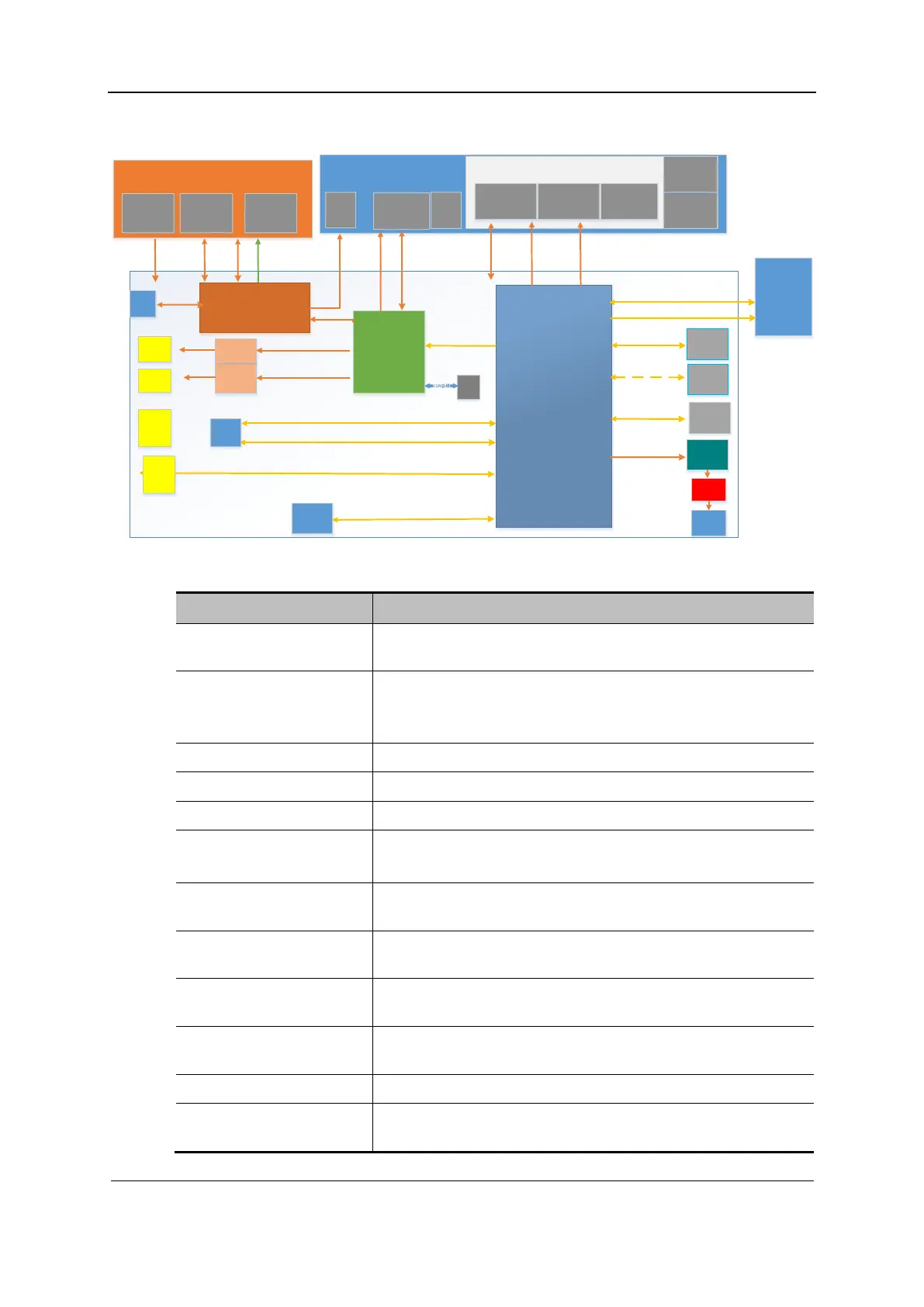
Fig 2-4 Block diagram of the backend
LCD
Light
Sensor
UI
Console board
Console_MCU LED & Drivers
Touch Panel
TCG Module
TrackBall
Module
FPGA
PC module
SATA BUS
PCIE*2 GEN2
USB3.0
USB2.0
HAD BU S
eDP
eDP
HDMI
RGB
S-Video
chip
CB_RST_N
Codec
Ethernet
PCIE*1 GEN1
S-video
WIFI
SSD
HDMI
USB3.0
*4
LAN
S-video
Back-end module
eDP/DP
USB2.0
Power module
Back-end
power
supply
Power
on/off
manag
ement
Ambient
light
sensor
2.5' HD D
SATA BUS
MCU
System
monitoring
I2C
DDR
Battery
charge/
discharge
DC-DC
PHV
Charge and
discharge
manageme
nt
Front-
end
module
redriver
HDMI
USB3.0
HUB
On/off
and
status
indicati
on
OLED
SPI/I2C
Power
amplifier
Speaker
Fan
FAN_CTL
FAN_TECH
4G
module
USB2.0
Function description:
Circuit Unit Function
Power-on/off control Controlling the startup and shutdown of the system. A power
indicator is provided.
System monitoring Battery management, fan control, voltage detection, battery
indicator control,
voltage detection, and temperature detection
Wireless network adapter Wi-Fi and Bluetooth functions
Wired network Supporting 10/100/1000M adaptive wired network.
USB port Providing four external USB 3.0 ports.
SATA interface SSD, m.2 type
2.5" standard disk interface
HDMI Providing an HDMI interface and supporting 1920 × 1080 HD
output.
S-Video Providing a standard S-Video interface and supporting NTSC
and PAL.
Audio Audio codec, power amplification, supporting 4-ohm 2W stereo
speaker.
FPGA Connecting between the industrial control board and the
ultrasound functional circuit.
Control panel interface Connecting the control panel, 12.3-inch touch screen display.
LCD interface Connecting the LCD display and image screen board and
supporting ambient light detection.
 Loading...


