ADJUSTMENT AND OPERATION
13-2
1. Inspection and adjustment of engine
1.1 Inspecting and adjusting valve clearance
1.1.1 Preparation for valve clearance inspection
(1) Inspect and adjust the valve clearance when the engine
is cold.
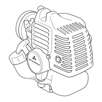
(2) Slightly loosen cylinder head bolts and tighten them to
the specified torque in the order as shown in the
illustration.
Tightening order of cylinder head bolts
1.1.2 Inspecting valve clearance
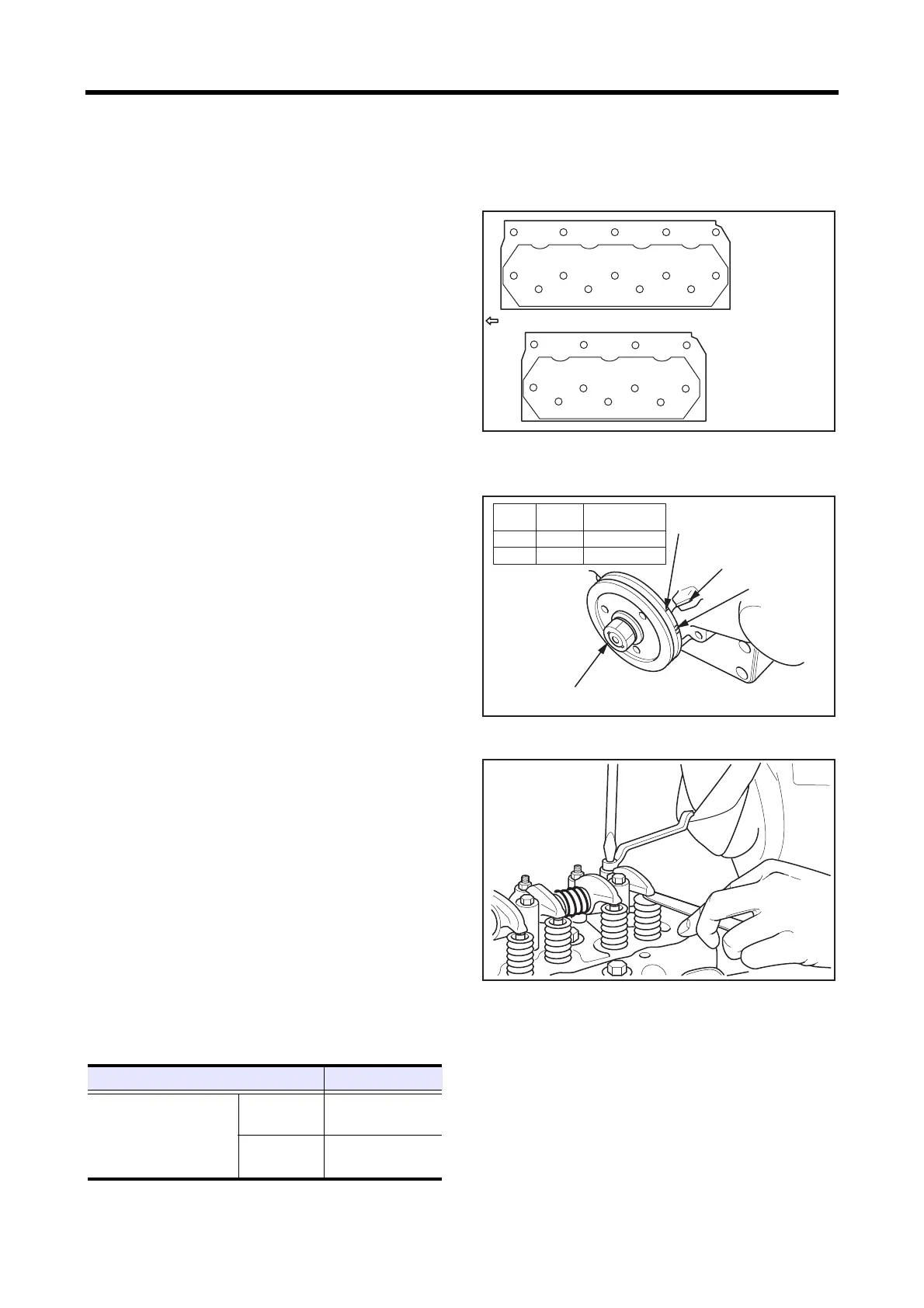
(1) Set No. 1 cylinder to the top dead center in compression
stroke.
This position is where the TDC mark on the crankshaft
pulley aligns with the mark on the gear case.
Note: The compression top is where the rocker arm does not
move when the crankshaft is rotated in the forward
and backward direction by both 20°approx.
If the rocker arm moves, it is the top dead center in
exhaust stroke. Rotate the crankshaft another full turn
to set the No. 1 cylinder to the top dead center in
compression stroke.
(2) Start adjusting the valve clearance from the No. 1
cylinder and adjust the valve clearance of other
cylinders according to the ignition order.
Note: To set the next cylinder to the compression top after
adjustment of No. 1 cylinder, rotate the crankshaft in
the forward direction (clockwise toward the timing
gear case) by the angle corresponding to the number
of cylinders.
(3) Insert a thickness gauge between the rocker arm and
bridge cap.Turn the adjusting screw while measuring
the clearance, and adjust the clearance so that the
thickness gauge can move with slight stiffness.
(4) After adjustment, tighten the lock nut firmly. Then,
check the clearance again.
Timing mark
Adjusting valve clearance
13
11
12
14
1
7
9
6
4
3
5
10
8
2
11
1
7
9
6
4
3
5
10
8
2
S4L,S4L2
S3L,S3L2
Front of engine
83.4 to 93.2 N·m
{8.5 to 9.5 kgf·m}
[61.5 to 68.7 lbf·ft]
Item Standard
Valve clearance
Inlet
0.25 mm
[0.0098 in.]
Exhaust
0.25 mm
[0.0098 in.]
TDC mark for No.1
and No.4 pistons
Counter mark on
gear case
TDC mark for No.2 and No.3 pistons
IT mark
Crankshaft
rotation angle
S3L 1-3-2 240°
S4L 1-3-4-2 180°
Model
Firing
order
18.0 to 22.0 N·m
{1.8 to 2.2 kgf·m}
[13.0 to 15.9 lbf·ft]
 Loading...